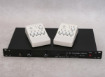
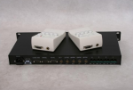
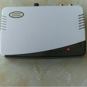
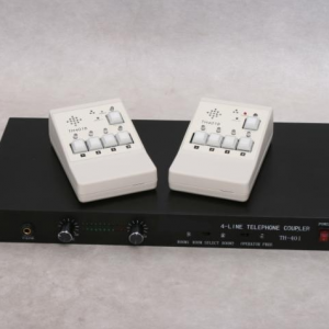
This product is a professional hotline telephone hybrid coupler. It is specially used by various radio stations and TV stations in live broadcast programs, and is also suitable for conference calls, telephone recordings and other occasions.
Provides four-way telephone access, adopts microcomputer chip and electronic switch technology, each control is independent of each other, the switch-in and switch-out operation is convenient and flexible, and four-way telephone access can be realized at the same time. It can be used to make multi-party calls and free conversations, and can also hold calls and talk separately.
It provides audio and control interfaces for the main and backup live studios. Users only need to add a control box and corresponding control cable to realize the time-sharing of a set of hotline devices between the two live studios.
Each channel is equipped with a sidetone adjustment switch, which can obtain better phone quality and avoid harmful sound feedback.
There are built-in communication devices in the director and host control box, including microphones and speakers (the host can switch the call output to the mixer or headset splitter), and there is a call button, which makes internal calls very convenient.
When there is only one host, the no-director function can be used, as long as the no-director switch on the front panel of the host is turned on (the indicator light is off at this time)
Technical indicators
Audio input: (from the studio) 600Ω balanced 0dB 6.35 three-pin plug
Audio output: (to the studio) 600Ω balanced 0dB 6.35 three-pin plug
(mixed output) 600Ω unbalanced -10dB 6.35 three-pin plug
(Headphone) 100Ω 6.35 three-pin plug
(Intercom output) 4Ω unbalanced-10Db 6.35 three-pin plug
Frequency response: 300Hz—3400Hz
Distortion: ≤1%
Signal-to-noise ratio: ≥70dB (excluding telephone line noise)
Sidetone suppression: ≥45dB
Host size: 1U standard chassis
Power consumption: 10W
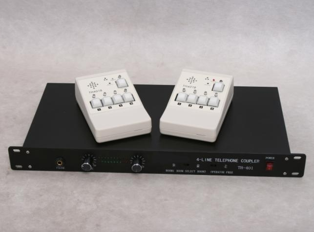
1: Headphone jack
2: Headphone level adjustment knob
3: Send the signal size adjustment button to the telephone line
4: Live room 1 and live room 2 selection instructions and live room 1 and live room 2 selection switches
5: Power switch
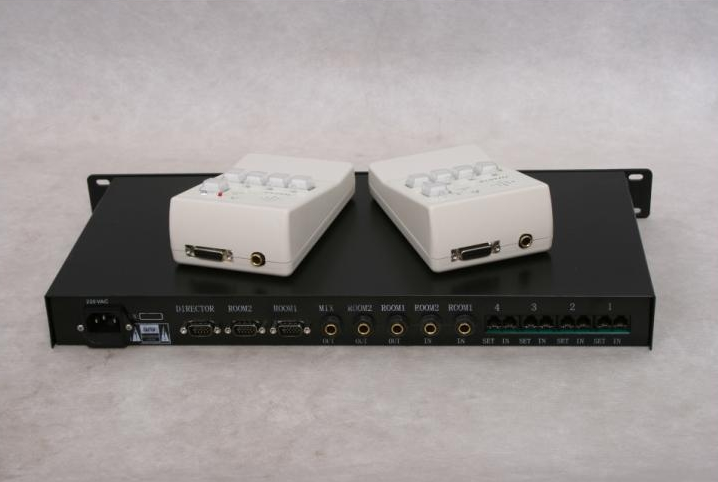
6: Power socket (fuse)
7: Control cable interface
8: Audio input and output interface
9: Telephone outside line and telephone interface
10: There is no director selection switch, the light is on for a director state (the switch is on the left), and the light is off for a non-director state. (The switch is on the right)
Installation and debugging
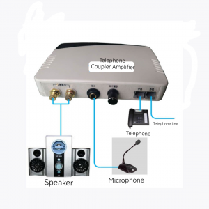
1: It is recommended to install the host in the director’s room, LINE to receive the outside line, and PHONE to receive the director’s call.
2: The director control box is connected to the DIRECTOR control port of the host, and the live studio control box is connected to the ROOM1 and ROOM2 control ports of the host. (Note: The director control box and the live studio control box are the same, but the control port of the connected host is different)
3: Connect the audio output (ROOM1 OUT and ROOM2 OUT) of the host to a line input module of the live mixer (balanced connection, if the mixer is unbalanced input, please connect the 6.35mm microphone plug of the host The middle ring is left in the air), and the host audio input (ROOM1 IN and ROOM2 IN) must be taken from the auxiliary output (AUX OUT) of the live mixer, and the corresponding auxiliary AUX control volume of the live mixer hotline input module should be adjusted to 0 (minimum), this is done to avoid unwanted acoustic feedback. Mixed output (MIX OUT) can be used to connect the power amplifier for studio monitoring.
4: Noise cancellation debugging
Position map of side noise adjustment switch and potentiometer
Before the official use, the test tone must be canceled, the audio test signal (working level) must be added to the hotline device through the line input, and the line output (ROOM OUT) of the hotline device must be connected to an electronic millivoltmeter to dial a certain number of telephones. And cut in (see below for the specific operation method), you can see that the millivolt meter has a small reading, open the chassis, and adjust the corresponding sidetone matching resistance and capacitance of the channel according to Figure 3 (controlled by the toggle switch, binary , as shown in the figure, the left side is the high position, the right side is the low position, there are 26 combinations from 2200PF to 0.2uF), so that the reading of the millivolt meter is the smallest. Repeat debugging and complete the adjustment of the other 3 channels.
5: During the call, adjust the SEND LEVEL to a suitable place to make the volume of the hotline listeners moderate.
6: Installation and adjustment of intercom:
After the director control box and the live room control box are installed, the intercom can be used. How to use: press and hold “TALK”
Button, speak into the microphone, the other party can hear it, the speaker volume adjustment can be achieved by inserting a screwdriver through the upper hole (SPEECH LEVEL); channel), lead the speaker signal to the mixer or headphone splitter, and monitor it through headphones.
Operation method:
● Incoming calls: When a call comes in from a certain channel, the telephone of that channel will ring, and the corresponding light-emitting tube on the director control box will flash, indicating that there is a call coming in, and the director can answer the call from this channel.
● Waiting for broadcast: When the director decides to switch to this channel after answering the call, just press the button corresponding to this channel on the control box, the green light is on, at this time, the hotline listeners can hear the live program, but cannot participate in the program for the time being. When you want to exit a certain channel from the waiting state, just press it once and the green light will go out, that is, it will exit the waiting state.
● Broadcast: The host presses the corresponding button according to the instructions of the green light on the live control box, the green light turns red, and the hotline listeners begin to participate in the program.
● Exit: After the call is over, the host presses the button again, the red light turns into a flashing green light, and enters the exit state, reminding the director to cut off the call. Outgoing call. The host can also press and hold the button, after 1 second, the red light will go out, and the call will be automatically cut out.
● Multi-party call: When a channel enters the broadcast state, switch to one or more channels to realize multi-party calls, and can discuss issues and other activities. The operation method is the same as that of single channel.
● Call Hold: When the host is talking with a listener, if he wants to temporarily interrupt and answer or make other calls, he only needs to temporarily enter the exit state (flashing green light), and to resume the call, press Just click this button.
Emergency cut out: whether it is the director or the host, press the button for more than 1 second, the line will be automatically cut out.
No guide: When using the function without guide, turn on the switch without guide on the front panel of the main unit, and the corresponding indicator light of the control box in the live broadcast room flashes when the call comes, and the host can directly press the corresponding button to connect to the audience hotline , and at the same time can communicate with the audience directly through the microphone (at this time, the indicator light on the control box is always on red, and it is in the broadcasting state). (There is an indicator light on the right side of the non-director switch, when the light is on, the no-director function is canceled, and when the light is off, the no-director function is enabled)
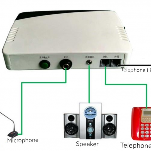
Note: the connection method of the telephone line: LINE to connect the phone
PHONT to answer the outside line
Packing List
●Telephone hybrid 1 set
●Control box 2 sets
●Control cable 2 pieces
●Operation manual 1 copy
●Power cord 1 piece
●Telephone lines 4 pieces



Reviews
There are no reviews yet.