1.1 Definition and Function of Antenna
Definition: A device that can effectively radiate electromagnetic waves to a specific direction in space or effectively receive electromagnetic waves from a specific direction in space;

An antenna (antenna) is a transformer that converts a guided wave propagating on a transmission line into an electromagnetic wave propagating in an unbounded medium (usually free space) (converting electrons into photons), or vice versa. A component used in radio equipment to transmit or receive electromagnetic waves. The radio frequency signal output by the radio transmitter is sent to the antenna through the feeder (radio frequency cable), and radiated out in the form of electromagnetic waves. After the electromagnetic wave reaches the receiving point, it is received by the antenna and sent to the radio receiver through the feeder. Generally, antennas are reversible, that is, the same antenna can be used as both a transmitting antenna and a receiving antenna. The basic characteristic parameters of the same antenna as transmitting or receiving are the same. This is the reciprocity theorem for antennas.
1.2 The basic principle of the antenna
The antenna uses an LC loop as a resonant loop, because the LC loop can have a much higher “quality factor” than the RC loop, and the general LC loop quality factor can reach tens to hundreds. A resonant circuit with a quality factor greater than 1 can absorb and “amplify” (actually convert) external signals, and a circuit with a quality factor of several hundred can induce a strong “oscillating signal” under a very weak external electric field condition; According to Maxwell’s electromagnetic field theory, a changing electric field produces a changing magnetic field in its surrounding space, and a changing magnetic field produces a changing electric field. In this way, the changing electric field and the changing magnetic field depend on each other, excite each other, generate alternately, and radiate from near to far in space at a certain speed.
For the symmetrical dipole antenna fed by the midpoint, its structure can be regarded as an open-circuit transmission line stretched out. A parallel two-wire transmission line with an open terminal, on which the current is distributed as a standing wave, as shown in the figure. The direction of the current on two parallel wires is opposite, and the distance d between the two wires is much smaller than the wavelength. The electromagnetic fields excited by them cancel each other out in the surrounding space outside the two wires because the phases of the currents on the two wires are opposite, and the radiation is very weak. If the ends of the two wires are gradually flared, as shown in the figure, the radiation will gradually increase. When the two wires are fully stretched, as shown in the figure, the current direction on the two stretched arms is the same, and the radiation is obviously enhanced. The unopened part behind the symmetrical vibrator is used as the feeding transmission line of the antenna
The basic radiating unit of the antenna: a half-wave symmetric vibrator, and a vibrator with two arms of equal length is called a symmetric element. The vibrator whose length of each arm is 1/4 wavelength and the total length is 1/2 wavelength is called a half-wave symmetric vibrator. The longer the wavelength, the larger the half-wave oscillator. The vibrator (wire capable of generating radiation) half-wave vibrator is used as the vibrator of the antenna, antenna feeder or antenna array in the short wave, ultrashort wave or microwave band.

The wavelength of the conductor is l/2, where l is the wavelength of the electrical signal. The signal generator supplies power to the antenna at its center point through a transmission line (also known as the antenna feed). Following this length, a standing wave of voltage and current will be formed across the wire
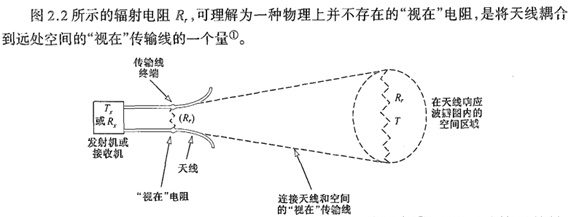
The electrical energy input to the antenna is converted into electromagnetic radiation and radiated into the air at the corresponding frequency. The antenna is powered by an antenna feed with a characteristic impedance of 50 Ω and a space with a characteristic radiation impedance of 377 Ω;
Question: Why is the total length of the antenna oscillator l/2?
There are two very important things to note about the antenna geometry:
1. Antenna length
2. Antenna feed
Antennas of length l/2 are called dipole antennas. But in printed circuit boards, most of the conductors used as antennas are only 1/4 in length, but still have the same performance
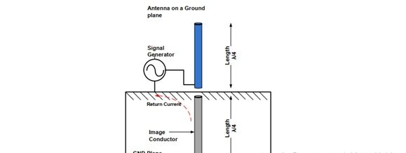
By placing a ground plane some distance below the conductor, a mirror image (l/4) of the same length as the conductor can be created. When grouped together, these pins act as a dipole antenna. Such antennas are known as quarter-wavelength (l/4) antennas. Almost all antennas on the PCB are implemented at a quarter-wavelength size on a copper ground plane. Note that the signal is now fed single-ended, while the ground plane is used as the return path;

Special attention: After actual simulation, the resonant frequency point of the microstrip antenna is not 1/4, but about 1/4*0.75, so when doing microstrip antenna simulation, generally take 0.8 of 1/4 of the antenna in vacuum times and the l/4 length of the microstrip antenna to traverse;
1.3 Classification of Antennas
Antennas come in many forms. For ease of discussion, they can be classified according to different situations.
1. According to the nature of work, it can be divided into transmitting antenna, receiving antenna and shared antenna for sending and receiving.
2. Classification by purpose
There are communication antennas, broadcast antennas, TV antennas, radar antennas, navigation antennas, direction finding antennas, etc.
3. Classified by antenna characteristics
■ In terms of directionality: directional antenna, omnidirectional antenna, needle beam antenna, fan beam antenna, etc.
■ In terms of polarization characteristics: wired polarized antenna, circular polarized antenna and elliptical polarized antenna. Linearly polarized antennas are further divided into vertically polarized and horizontally polarized antennas.
■ In terms of frequency band characteristics: there are narrow-band antennas, wide-band antennas and ultra-wide-band antennas.
4. According to the current distribution on the antenna, there are traveling wave antennas and standing wave antennas.
5. There are long-wave antennas, ultra-long-wave antennas, medium-wave antennas, short-wave antennas, ultra-short-wave antennas and microwave antennas according to the bands used.
6. According to the carrier, there are vehicle-mounted antennas, airborne antennas, satellite-borne antennas, and missile-borne antennas.
7. Classified by antenna shape
There are whip antennas, T-shaped antennas, Γ-shaped antennas, V-shaped antennas, rhombic antennas, loop antennas, helical antennas, waveguide port antennas, waveguide slot antennas, horn antennas, reflector antennas, Yagi antennas, log-periodic antennas, arrays antenna. Array antennas include linear array antennas, planar array antennas, conformal array antennas attached to the surface of some carriers, and the like.


