
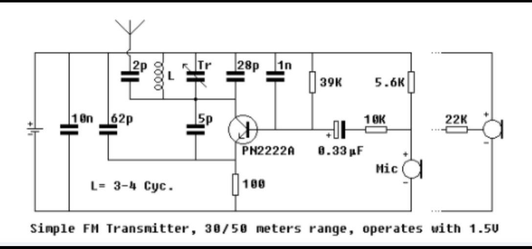
This is a mini FM transmitter circuit. I think this is the simplest, easiest and of course…cheap… The supply voltage is between 1.1 – 3 volts and the power consumption is 1.8 mA at 1.5 volts. This circuit should be covered, right? Maximum range 30 – 50 meters. at 1.5 volts.

transmitter circuit
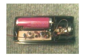
The main advantage of this circuit is that the power source is a 1.5 volt battery (of any size), allowing the PCB and battery to be held in a very compact place. The transmitter can even run on standard NiCd rechargeable batteries, for example a 750mAh AA size battery can run for about 500 hours (while it’s pulling 1.4mA at 1.24V) which equates to 20 days.
The transistor is not a critical part of the circuit, but choosing a high frequency/low noise transistor can help improve the transmitter’s sound quality and range. PN2222A, 2N2222A, BFxxx series, BC109B, C, and even the well known BC238 work perfectly. The key to a well-functioning, low-power circuit is to use high hFE/low Ceb (internal junction capacitance) transistors.
Not all condenser microphones have the same electrical characteristics, so after operating the circuit, use a 10K variable resistor instead of 5.6K, which supplies the current to the microphone internal amplifier and adjusts it to the sweet spot for the sound with the best amplitude and quality . Then note the value of the variable resistor and replace it with a fixed resistor.
The key part is the inductor L which should be made by hand. Take a piece of 0.5mm (AWG24) enameled copper wire and wrap two 4-5mm diameter loosely into a circle. Wire sizes may also vary. The rest of the work depends largely on your knowledge and experience level with inductors: Install an FM radio near the circuit and set the frequency where there is no reception. Apply electricity to the circuit and place an iron rod into the inductor loop to determine its value. When you find the correct point, adjust the looseness of the inductor and, if necessary, the number of turns. Once everything is working fine, you can use the trimmer capacitor to make further frequency adjustments. At this point, you may be able to get help from someone with experience. Don’t forget to secure the inductor against external forces by pouring some glue over it. If radio reception is lost within a few meters, this may be caused by incorrect coil adjustment and you are actually listening to the harmonics of the transmitter rather than the center frequency. Move the radio away from the circuit and readjust it. It’s easier if you know how to use an oscilloscope in this situation.
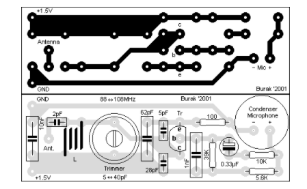
Each part should be easy to install on the underlying PCB. Note that the transistor leads should be connected correctly. Also try connecting the moving part of the trimmer capacitor to the + side, this may help with unwanted frequency shifts when tuning. The PCB diagram should be printed at 300DPI, and a TIFF file has been set up here.
Mini FM Transmitter PCB Layout:
transmitter circuit
Technical data:
Supply voltage: 1.1 – 3 volts
Power consumption: 1.8 mA at 1.5 volts
Range: up to 30 meters. at 1.5 volts
transmitter circuit


