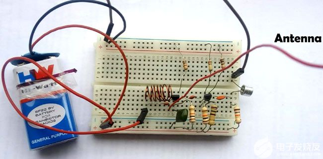
The miniature FM transmitter circuit introduced here is a kind of miniature wireless FM microphone.
It uses a dual-tube push-pull transmission circuit, and the transmission frequency is set at the 88~108MHz civil FM radio frequency band, and the signal can be received by using an ordinary FM radio.
Circuit principle
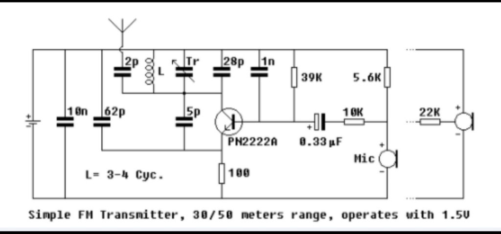
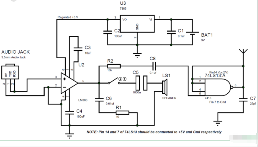
As shown in the figure below, it is the circuit diagram of the miniature FM FM transmitter.

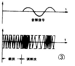
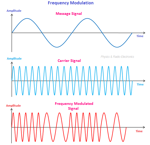
The circuit includes audio conversion and high-frequency oscillation modulation. The electret microphone BM picks up the external audio and converts it into an electrical signal, which is coupled to the high-frequency oscillation circuit via C1 for FM modulation. The collectors and bases of the two triodes VT1 and VT2 are cross-connected to each other, and form a resonant circuit with L and C2 to form a high-frequency oscillator. The oscillation frequency is determined by the junction capacitance of the triode, L, and C2. The audio signal coupled by C1 will change the junction capacitance of the triode, causing the parameters of the resonant circuit to change, thereby modulating the oscillation frequency, so that the frequency change follows the audio signal. Variety. The modulated FM signal is coupled to the antenna through C3 and transmitted.
Selection and production of components
The resonant inductor L needs to be self-made, as shown in the figure below.
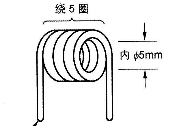
Manufacture of resonant inductor
For the resonant inductor L, use a 0.5mm enameled wire directly on the 5mm diameter drill shank as a skeleton to wind 5 turns, then draw it out to form a hollow coil, and stretch it properly. The pads of electret microphones generally do not have installation pins, and you can use wires or resistor pins as installation leads according to your own installation needs, as shown in the figure below.
The install the pins for the electret microphone
For the transmitting antenna, you can use a 30cm~50cm flexible wire.
Circuit debugging
The first step of debugging is to determine whether the circuit is oscillating, as shown in the figure below, when there is no oscilloscope, you can use a multimeter to simply check whether it is oscillating.
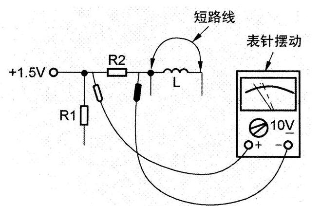
The detection method of oscillator start-up without oscilloscope Try to use a pointer multimeter, place the DC 10V gear, and measure the voltage drop of R2. When measuring, short-circuit L with a wire and touch it. This can force the circuit to switch back and forth between oscillation and stop, so as to judge whether it starts to oscillate. The second step of commissioning is to modulate the transmission frequency, as shown in the figure below.
Adjustment of transmission frequency
Adjust the spacing of each turn of L to change the transmission frequency. Use FM to tune the radio, set a frequency with no radio stations, and then adjust the spacing of L until the radio receives a signal.
