The exciter of the FM302E-I type FM transmitter adopts the HPB-1210 motherboard of Japan NEC Company. Direct frequency modulation of the carrier, using phase-locked frequency stabilization and frequency synthesis technology. The pre-stage power amplifier (BLF-177 field effect tube) is directly driven by the exciter, and the maximum output power is 150W. Through the circulator to the final stage, it is used as the driving stage of the final tube power amplifier.
The integrated power supply and power amplifier tube are relatively expensive, and the loss is very large. Therefore, it is necessary to add an overvoltage protection circuit to the power amplifier tube of this stage, especially because my station is located on a high mountain. During the thunderstorm season in summer, the power line is often connected by lightning, which burns out the transmitting equipment. Coupled with an overvoltage protection circuit, it is safe and high-quality broadcasting, reduces the stoppage rate, and can save a lot of money.
The FM transmitter is a device that modulates the audio signal and the high-frequency carrier into a frequency-modulated wave, so that the frequency of the high-frequency carrier changes with the audio signal, and then amplifies the generated high-frequency signal, excites, power amplifiers and a series of impedance matching , so that the signal output to the antenna, sent out of the device.
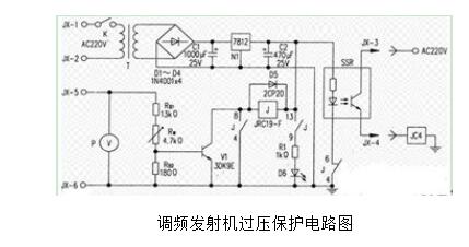
Here is a circuit diagram of an FM transmitter overvoltage protection.