
Describtion:
FM transmitters have been used for communications all over the world. The simplicity of building FM circuits is what makes it so popular among other modulation techniques. Today I came up with FM transmitter circuit, its range is about 3 km. The circuit diagram is very wide and I can’t fit it into this web page. Click on it to view the high-resolution image. Let’s get into the working part of this circuit.
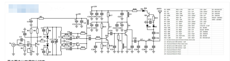
Transmitter circuit
Working principle of FM transmitter:
There are a lot of components and parts in this circuit, so I’ll keep the explanation as simple as possible. This is a good quality FM transmitter with stable frequency brought about by an improved oscillator, which is actually two oscillators built around Q2 and Q3, operating at around 50MHz. The output is taken on both collectors, where the frequencies of the two oscillators combine to form a 100MHz signal. This will provide greater stability than a normal single-ended oscillator.
Modulation is completed through double variable capacitors D1/D2 and variable capacitor C8. By changing the reverse bias voltage on the variable capacitors (based on the input signal), you essentially change their capacitance and thus the resonant frequency of the resonant circuit. This results in virtual frequency modulation of the input signal. The output of the oscillator/modulator stage is fed to a class A driver stage built using transistor Q4. The output signal is further enhanced by feeding into a Class C power amplifier built around Q5.
Now feed the output signal from Class C to a low pass filter consisting of a series of capacitors and inductors. This is done to achieve the lowest harmonic spurs at the output before feeding it to the antenna. I added an indicator LED D3 to show you are transmitting and everything is fine. If the LED does not light up, there is something wrong with the schematic. The problem usually occurs in the oscillator section (just a hint). Also, I managed to remove almost all the variable capacitors except the ones used for tuning, since the original schematic had more variable capacitors and it was difficult to tune them all.
FM circuit range:
The output signal power in this FM circuit is 2.5W. At 2.5W, the FM signal can cover a distance of 5-7 kilometers with good line of sight. In the best case, it might even reach about 10 kilometers. So I believe it’s fair to say that even in semi-optimal or worst outside conditions the track will cover 3km of range.
This circuit is designed for European FM receiver systems, and although it will work in the US as well, I’m not sure if the audio quality will remain the same. This is because I used 50us pre-emphasis, which is the European standard, while the US uses 75us pre-emphasis.
Circuit board tips:
There are some PCB considerations you must follow when building this circuit. When wiring a system, it is important to use a ground plane rather than a ground rail. This increases floor area and stability. You can also build a balun by coaxing 3 or 4 turns of 21-inch length coax before the antenna feed. Therefore, this will create a resonant trap for the electric field flowing on the cable jacket and prevent it from entering part of the antenna, which is undesirable.
Notice:
Never start the transmitter without load.
If you haven’t connected the antenna yet, just put a 2 ohm dummy load resistor at 50W (carbon, not wire) and test your circuit.


