
I introduced a Github project of a very interesting wireless FM radio station, which can turn the Raspberry Pi into a small FM radio station through code without borrowing other external devices.
But the author only introduced the general principle in the blog. I searched the entire network and found that most of the relevant articles only teach you how to compile and run the code, but the principle behind it is only a few words and vague.
As a curious baby, I consulted many chip manuals and forum articles, and flipped through the “Antenna Principles” I had learned before to summarize and summarize the principles behind it.
concept noun explanation
First some basic concepts
FM: Frequency Modulation (Frequency Modulation) is a modulation method that uses the instantaneous frequency change of the carrier to represent information. The frequency of the carrier changes directly in proportion to the amplitude of the input signal. FM Radio is the FM radio we are familiar with.
FM modulation
PWM: Pulse Width Modulation (Pulse Width Modulation) is a method of generating an analog signal using a digital source. It is mainly defined by 2 parameters: duty cycle and frequency. If a digital signal is switched at a constant rate and with a constant duty cycle, the output will look like a constant voltage analog signal.
PWM
GPIO: General-purpose input/output (General-purpose input/output), the pin can be controlled by the program as a general-purpose input (GPI) or general-purpose output (GPO).
RPI GPIO
CPU: Central Processing Unit (Central Processing Unit), which is equivalent to the brain of the Raspberry Pi. Its main function is to interpret computer instructions and process data in computer software, and is responsible for communicating with peripheral devices. The Raspberry Pi uses a Broadcom BCM28XX series CPU.

BCM2837
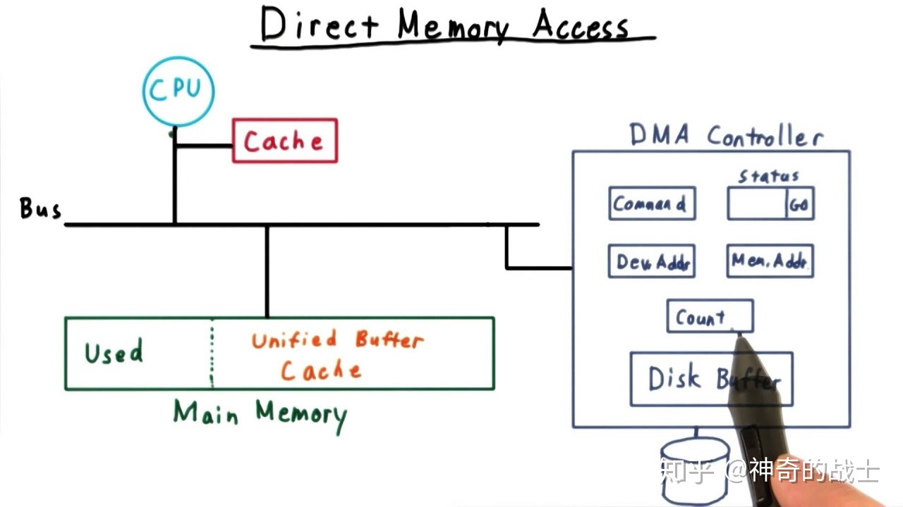
DMA: Direct Memory Access These devices can perform data transfers involving main memory and other devices. Because the device performs these operations without the help of the CPU, this type of data transfer is called direct memory access. Simply put, it means that you can directly access the memory without saying hello to the CPU.

DMA
HOW?
According to Maxwell’s electromagnetic field theory
1. A changing magnetic field can generate an electric field in the surrounding space, and a changing electric field can generate a magnetic field in the surrounding space.
2. A magnetic field (electric field) that varies uniformly with time produces a steady electric field (magnetic field). A magnetic field (electric field) that varies inhomogeneously over time produces a changing electric field (magnetic field).
3. The changing electric field and the changing magnetic field are always related to each other, forming an inseparable unity, which is the electromagnetic field.
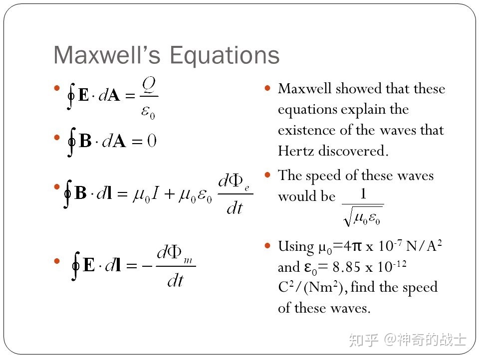
Maxwell’s equations
A time-varying electric field produces a magnetic field, and a time-varying magnetic field produces an electric field, and the two cause and effect each other. This constantly transforming field is collectively known as the electromagnetic field. This mutual transformation forms electromagnetic oscillations.
Therefore, if the GPIO of the Raspberry Pi is controlled by software to output high and low levels (0/1) at a certain frequency, coupled with an antenna of appropriate length (a Dupont cable is enough), the energy can be emitted in the form of electromagnetic waves. go out.
FM structure diagram
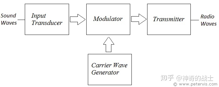

FM Transmitter Block Diagram
As can be seen from the figure, to form an FM transmitter system, the Raspberry Pi needs
Clocks required for signal sampling and FM modulation
Programmable level-changing GPIOs
An antenna that emits electromagnetic waves
clock
At present, most of the microprocessors have a spread-spectrum clock (Spread-spectrum clock), the purpose is to reduce electromagnetic interference (EMI). On the Raspberry Pi BCM28XX series chips, the range of the spread-spectrum clock is 1MHz to 250MHz. This works exactly as the carrier signal for FM.
In order to reduce the CPU usage, the author improved the program and used the Raspberry Pi DMA to generate the basic clock.
clock signal
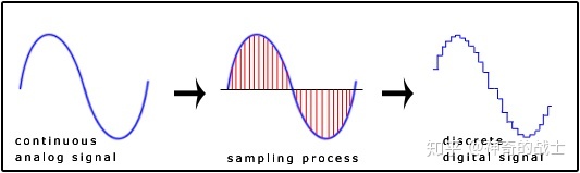
signal sampling
Since FM radio sends audio signals, the signal is first sampled using a sampling frequency of 228 kHz (to satisfy the Nyquist sampling theorem) with a bandwidth of 15 kHz.
signal sampling
FM
The baseband signal xm(t) , the carrier frequency fc , and the sinusoidal carrier is xc(t)=Accos(2πfct) Combining the baseband data signal with the carrier gives the transmitted signal
y(t)=Accos(2π∫0tf(τ)dτ)=Accos(2π∫0t[fc+fΔxm(τ)]dτ)=Accos(2πfct+2πfΔ∫0txm(τ)dτ)
Where f(τ) is the instantaneous frequency of the transmitted signal, and fΔ is the frequency offset, which represents the maximum frequency offset relative to the carrier frequency fc.
The FM output is an analog signal. Using the clock to generate PWM to adjust the duty cycle and frequency, the digital signal can be used to generate an analog signal.
Raspberry Pi Antenna Length
Wavelength: λ=c/f
Dipole antenna: When making a dipole antenna, the length of the antenna will be determined by the operating wavelength. The most common dipole antenna is the half-wave antenna, whose total length is approximately half of the operating wavelength, that is, L=λ/2

If you need to transmit 100MHz FM signal, according to the above formula, you need a 1.5m long antenna.
>>> 3*10**8 / (2 * 100 * 10**6)
1.5
So in theory, if a 1.5m antenna is added to the Raspberry Pi GPIO (PIN4), then the FM signal with maximum power can be output.
Don’t do this, it will interfere with the normal frequency band!
propagation distance estimation
First you need to calculate the effective isotropic radiated power (EIRP)
EIRP=P−Loss+G
Where P is the output power of the transmitter (dBm), Loss is the feeder loss between the output of the transmitter and the antenna feed (dB), and G is the transmit gain of the antenna (dBi). After calculating the EIRP, the Free Space Path Loss (FSPL) can be obtained.
But it doesn’t make much sense to use this formula to estimate. In actual measurement, if a 10cm Dupont wire is used as an antenna, the signal at a stair corner is already very weak.
Summarize
I deeply admire the first author’s Geek Fan and Mo Da’s brain hole;
Do not interfere with the normal frequency band, it is illegal!


