
Building an FM transmitter and broadcasting our own signal on the radio is indeed a fun project. In particular, use this circuit because it doesn’t require you to wind your own inductor or use a trimmer and spend hours tweaking the circuit to make it work. In this project you’ll learn how an FM transmitter works and how to build your own using subtle components.
Required components:
The theme of this simple FM transmitter circuit is to build it with the minimum number of components available, without the use of inductive coils and variable capacitors, while allowing it to perform to its maximum potential. The components required to build this project are listed below
SN74LS13 – 4-Input NAND-Gate Schmitt Trigger
LM386 – Audio Amplifier
3.5mm audio jack
7805 voltage regulator
1000uf, 100uf, 10uf, 0.1uf, 22pf capacitors
9V battery
Breadboard
cable
Speakers used for testing
FM transmitter working principle:
Before we dig into the circuit and start building it, I think we should know how an FM transmitter works so that it makes sense when building it. If you’re not interested in the theory, you can skip this part and go to the circuit diagram.
An overview of the FM transmitter is given using the following block diagram
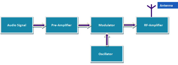
The term FM stands for “Frequency Modulation”, which means that we will change the frequency of the audio signal so that it can travel long distances in the air. Every audio device such as an IPod or music player produces audio signals in the form of sine waves; these are called modulating signals or modulating frequencies. This modulated signal has complete information about the song or music being played. But these guys are a week; they can’t travel long distances and will most likely die before reaching the receiver (radio).
So, we have to find someone who is really powerful and can actually pass these week modulated signals to their receivers. These strong signals are called carrier signals or carrier frequencies. We call this technique of combining a strong carrier frequency with a modulating frequency Frequency Modulation (FM). Here, the frequency of the carrier is modified according to the frequency of the modulating signal.
As shown in the block diagram above, the modulated signal is generated in the audio signal box and then amplified using a preamplifier. An oscillator produces a strong carrier frequency, and a modulator is used to modulate the signal to that frequency. To further increase the range, radio frequency amplifiers and antennas are used.
In our circuit, the audio signal is provided by a phone or iPod. Pre-amplification is done using the LM386 audio amplifier IC. The 74LS138 and the 22pF capacitor act as a resonant circuit that generates a strong carrier frequency and modulates it with our amplified audio signal. We don’t have an RF amplifier in our circuit, but it can be added if you need to achieve higher range.
Circuit diagram:
The figure below shows the circuit diagram of this simple FM transmitter.
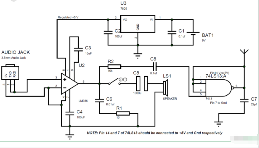
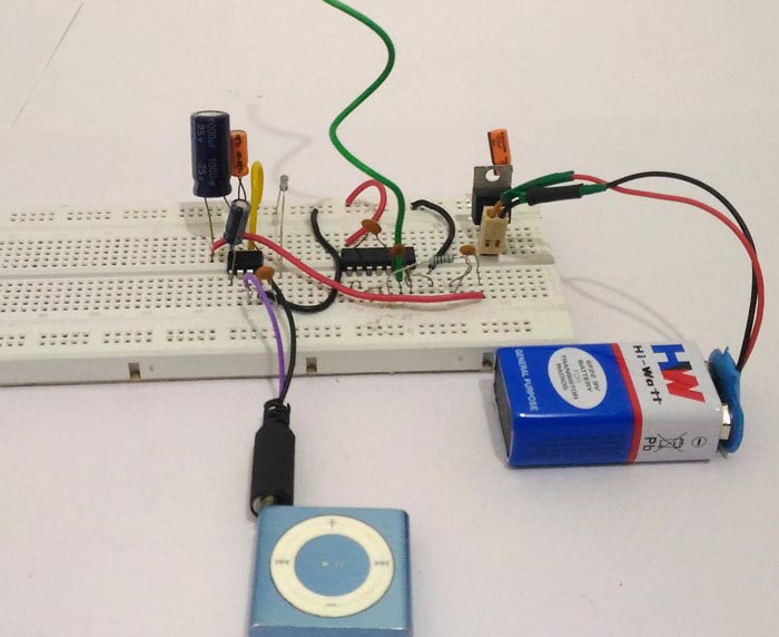
It can be built on a breadboard or soldered to a Perf board. The entire circuit can be powered from a 9V battery. If using an adapter to power it, be sure to add filter capacitors to reduce noise from switching. This circuit uses LM386 audio amplifier as a preamplifier, this IC amplifies the audio signal from the audio device and feeds it to the oscillator circuit.
The oscillation circuit should have an inductor and a capacitor. In our project, IC 74LS13 is a 4-input NAND-gate Schmitt trigger designed to have harmonics around 100Mhz at 3^RD^order. Filter capacitors on the IC power rails are very important to make it work.
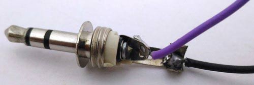
The 3.5mm audio jack has three terminals for channel L, channel R, and ground. We short the channel pins to make it mono as shown in the image below and connect it to pin 3 and ground to pin 2 of the LM386.
An 8 ohm speaker is used to test the amplifier circuit. This speaker should be disconnected while we tune the circuit.
Tuning to the correct FM band:
Due to Tony Van Roon’s method of tuning, this FM transmitter circuit is very easy compared to other circuits as it has no inductors or trimmers. To get started, just power up the circuit and connect the speaker to the circuit as shown in the circuit above. Now connect your iPod or any audio device to the 3.5mm jack and play music. You should be able to hear audio through the speakers. If not, the problem should be with your LM386 connection. If you can hear audio, disconnect the speakers and continue the tuning process.
Use a radio with a tuner and start turning the knob to find out what frequency the oscillator is broadcasting. Your best bet is to check around 100Mhz as it will most likely work around that frequency. Keep the volume on maximum and turn it up slowly until you can hear the song playing through the audio source. You can also watch the video below to see how I tweaked it.
Here’s what you can try if you’re hitting a wall:
If you hear a strange noise at a specific frequency and want to find out if that is your oscillator frequency. Just turn the circuit off and on again and your radio should crackle if the frequency is correct
Extend the radio’s antenna to its full length and initially position it close to the circuit
Change the operating voltage in the 4.5 to 5 V range to change the radio frequency as sometimes your frequency may conflict with another popular FM band.
(Totally optional) If you have a variable capacitor with a 0-22pf range, you can replace the 22pf cap with this trimmer and try changing its value.


