
BA1404 is a low-voltage, low-power design with a maximum power consumption of 500mW.
It integrates stereo modulation, FM modulation, and radio frequency amplification on one chip; it requires few peripheral components;
The two-channel separation is high, with a typical value of 45dB;
The input impedance is 540Ω (fin=1kHz), and the input gain is 37dB (Vin=0.5mV);
RF output can reach 600mV.
The circuit uses a very classic diagram, and a tuning amplification is added to the output at the back to meet the power requirements. Care should be taken here in the transmitter circuit not to have too much power. It is illegal if it is too large and affects other frequencies. High power is only legal in some frequency bands. I didn’t understand the law here, and the power at that time was generally high.
The stereo pre-stage is an audio amplifier for two channels. When the input is 0.5mV, the gain is as high as 37dB and the frequency bandwidth is 19kHz.
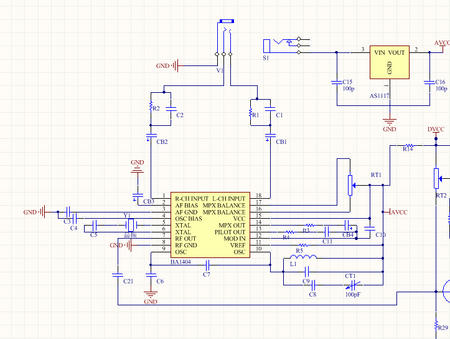
I was afraid that the output power of 1404 was not enough, so I added further amplification later.

The upright inductor in the picture above is adjustable. By changing it, it changes the resonance frequency, which is the frequency of the output end. It can be calculated based on the formula. But the inductance was not calculated at that time. So just tune in and use the radio to receive. Adjust the receiving frequency of the radio when fixing. As long as the sound I emit is correct. The pop-up effect is pretty good. In addition, it is important to pay attention to the parameters of the capacitor here, and the parameters in the subsequent amplification and tuning indicators need to be debugged step by step. It must have taken some time. Generally speaking, the sound received is quite clear.


