
Describe:
One cool project I’ve been wanting to build is an FM transmitter with a good range. I’ve always been fascinated by some applications of transmitters, especially when I was younger, and like everyone else, I spent most of my time imagining how cool it would be to use some devices and contraptions in spy movies. So recently, while checking out one of my home automation/security projects using a Raspberry Pi and the motion library, I thought it would be cool to add sound and live listening to the project, so I could get the video from being monitored in addition to the video feedback the Pi provided. The zone gets audio feedback. So during the ideation session to implement this Raspberry pi monitoring system, the idea of this FM transmitter came back to my head, and while it wouldn’t allow me to listen remotely (more than 10km away), it would at least allow me to be in the house Keep an “ear” around, and after building it, I’ll achieve some of my youthful goals. So a few days ago I finally found the strength to build it, and in today’s tutorial, will share how to build my own FM transmitter circuit, and trust me, it works just fine.
At this point, it’s important to point out that this is done for experimentation and learning purposes only, as the laws of some countries prohibit unauthorized broadcasting. Therefore, it is important to keep the FM transmitter low in range and make sure that it must be built within the legal framework of your country and will not be a nuisance to the public. I will not take any stake in any accident.
How an FM Transmitter Works
An FM transmitter is a device that broadcasts the sound provided at its input using the principle of frequency modulation. A typical FM transmitter design usually follows the block diagram below;

The signal strength of the audio input going into the transmitter is usually low, so amplifiers are often built to boost the signal level. Based on the desired frequency of transmission (typically between the FM band, 88MHz to 108MHz), an oscillator circuit is used to generate a carrier frequency and mix with the audio signal to produce a modulated signal. The modulated signal then passes through a power amplifier at the transmission stage to create a low impedance match to the antenna.
Components Required for FM Transmitter Circuit
Building this FM transmitter project requires the following components:
2n2222 NPN transistor x2
Condenser microphone/audio jack or any other audio input section
100nf ceramic capacitor x1
10nf ceramic capacitor x1
4 pf ceramic capacitor x1
100 ohm resistor x1
10k resistor x 3
1k resistor x 1
100k resistor x1
1M resistor x1
Variable capacitor 20pf
Gauge 18 – 22 copper wire
9v battery
9v battery capacitor
Most of these components can be recycled from old parts.
FM transmitter circuit diagram and description
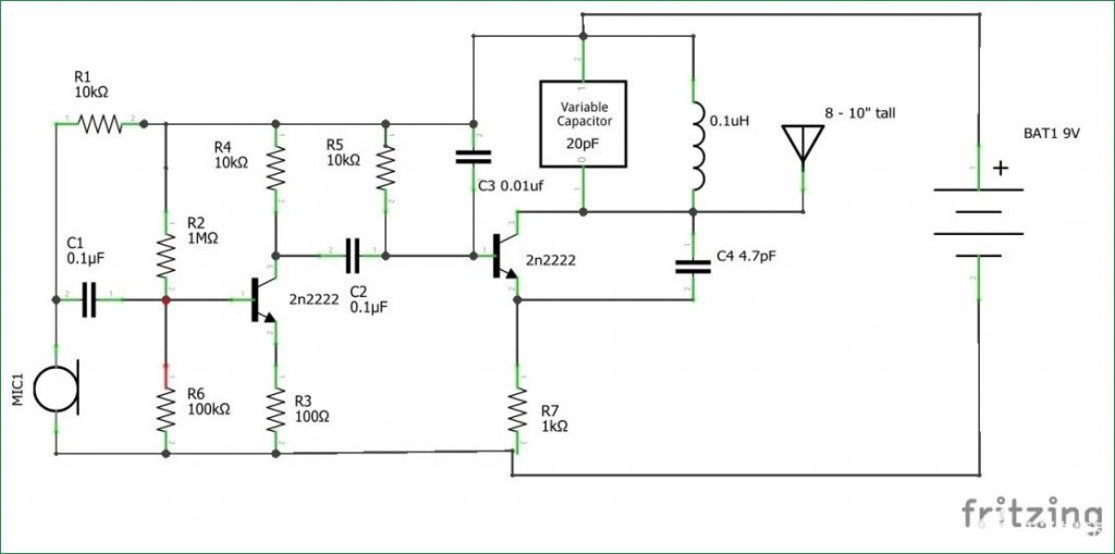
Connect the components as shown in the simple FM transmitter circuit below.
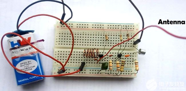
This is what this simple FM transmitter circuit looks like on a breadboard

The audio output signal from the microphone is usually small, so the first transistor does the job of amplifying that signal to a level sufficient for transmission. After amplification as described earlier, the next stage in the FM transmitter is modulation. In this stage, the amplified audio signal is mixed with the carrier frequency of the signal to be transmitted. This carrier frequency can be changed using a 20pF variable capacitor connected to the inductor, and the typical frequency band for this particular design is between 88MHz and 108MHz, and since there is no visual output to identify the exact frequency the transmitter is operating at, you will need to use the Tune the FM receiver radio in the above frequency range to obtain the frequency that the transmitter transmits. After modulating the audio signal with the carrier frequency, the signal is sent out through the antenna.
Air core inductors are made by wrapping 8 to 10 turns of 18 – 22 gauge wire around a 1/4 inch front that can be represented by a pencil. The component values used in these tutorials are not critical, and for learning purposes, you can use resistor and capacitor values to optimize the performance of the transmitter.
Apart from the above uses, FM transmitters along with this design can also be used to create baby monitors, school address systems, etc. Make sure to check the laws in your location before building any of these useful things.


