
1. Lifting the veil of the antenna
As we all know, antennas are used by base stations and mobile phones to transmit signals.
The English word for antenna is Antenna, which originally means tentacles. The tentacles are the two long filaments on the top of the insect’s head. Don’t underestimate such an inconspicuous thing. It is the chemical signals sent by these tentacles that insects transmit various social information.
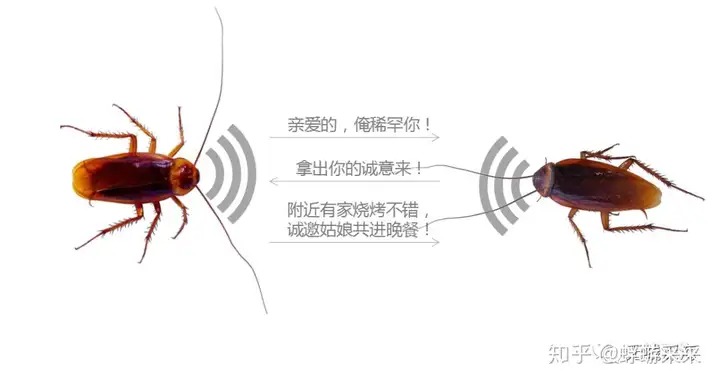
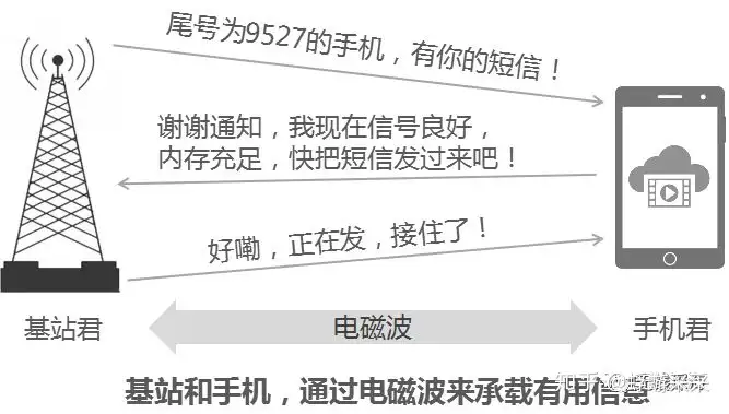
Similar to this, in the human world, wireless communication also transmits information through antennas, but what is transmitted is electromagnetic waves carrying useful information. The figure below is an example of the communication between the mobile phone and the base station.
So what does the actual antenna look like? Due to different uses, there are too many forms of antennas, ranging from large pots (parabolic antennas) that receive TV signals to small antennas hidden in mobile phones. They have different shapes due to different functions.
When it comes to antennas, the antenna most people see most often is the antenna of their wireless router at home.
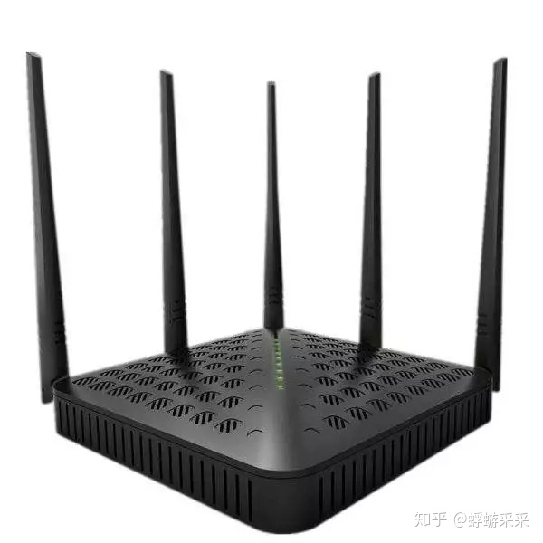
It is these stick-like antennas that allow us to enjoy the speed of flying.
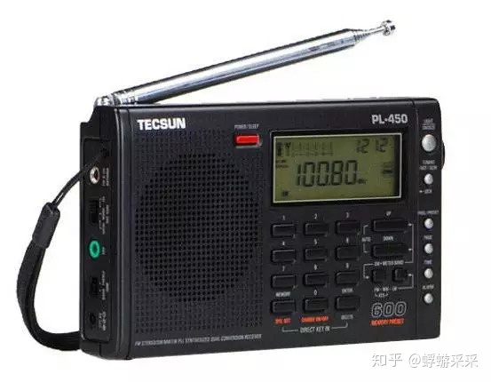
A long time ago, listening to the radio was a very fashionable thing. There is a long antenna on the radio that can be stretched one by one. This antenna is exactly the same as the router antenna. It is called a whip antenna, also called a telescopic antenna or a pull rod. antenna.
In prehistoric times, the tallest building in every city must be a TV tower, and TVs also receive signals from the TV tower through antennas. initial impression. Both the shape and the function are completely similar to the tentacles of insects.

In addition, there are all kinds of different types of antennas, and different types can be given according to different classification methods.
1. According to the nature of work, it can be divided into transmitting antenna and receiving antenna.
2. According to the purpose, it can be divided into communication antenna, broadcast antenna, TV antenna, radar antenna, etc.
3. According to the directionality, it can be divided into omnidirectional antenna and directional antenna.
4. According to the working wavelength, it can be divided into super long wave antenna, long wave antenna, medium wave antenna, short wave antenna, ultrashort wave antenna, microwave antenna and so on.
5. According to the structure and working principle, it can be divided into line antenna and planar antenna.
6. According to the number of dimensions, it can be divided into two types: one-dimensional antenna and two-dimensional antenna.
7. Antennas can be divided into three categories according to different usage occasions: handheld antennas, vehicle antennas, and base antennas.
Just like a blind man feeling an elephant, each classification method can only describe one side or one type of characteristics of the antenna. Only by combining all the characteristics targeted by these classification methods can the whole picture of the antenna be seen clearly.
In order to reduce the complexity, Mr. Mayfly will start with the most intuitive classification method. Seeing is believing, and let everyone see what real antennas for different purposes look like.
Many people should have seen this kind of antenna in the picture below. In the past, it was mainly mounted on the roof for TV signal reception (the whip antenna that comes with the TV is really limited). This kind of fishbone antenna is called Yagi antenna.
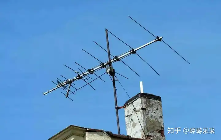
No need to count whether there are 8 rods on the antenna. The reason why it is called Yagi antenna is because its inventor is a Japanese named Yagi Hideji. Yagi antennas are mainly used for TV signal reception, and there are not many scenarios for wireless communication.
The picture below is a parabolic antenna for radar, like huge pots, it is spectacular. When the radar is launched, the energy must be concentrated and radiated to the direction that needs to be irradiated. This shape is very suitable.

The following “pots” are smaller, which are microwave antennas used to send and receive microwave signals to transmit information. Electromagnetic waves such as microwaves have very short wavelengths and mainly propagate in straight lines. The transmitting and receiving antennas must be aligned with each other to work. They are mainly used for transmission in wireless communications.
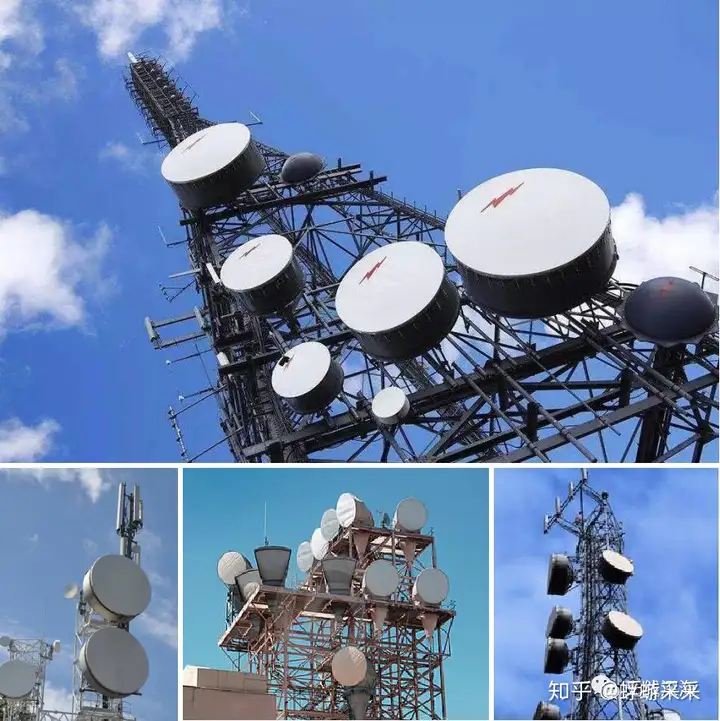
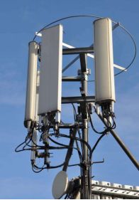
If you look at the above pictures carefully, you will find that there are some plate-shaped things on the top of the tower, which is the protagonist of this article: communication antenna (the subdivision type is directional antenna: the signal is sent and received in a certain direction), the most This is the one who often makes eye contact with the mobile phone.
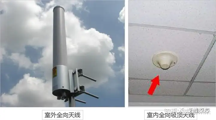
Since there are directional antennas, there must also be omnidirectional antennas. As the name implies, omnidirectional antennas can send and receive signals in 360° without dead angle, outdoor omnidirectional antennas, and ceiling antennas for indoor coverage.
Back to the protagonist of this article: the directional antenna. To uncover the mystery of this product, it is necessary to take it apart to see what is inside.
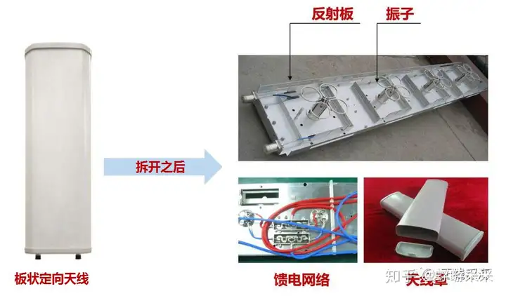
The interior is empty, and the structure is not complicated. It is composed of a vibrator, a reflector, a feed network and a radome. What do these internal structures do, and how can the function of directional transmitting and receiving signals be realized?
It all starts with electromagnetic waves.
2. Peel off the coat of the antenna
The reason why the antenna can transmit information at high speed is because it can launch the electromagnetic wave carrying the information into the air, propagate at the speed of light, and finally reach the receiving antenna.
This is like using high-speed trains to transport passengers. If information is compared to passengers, then the tool for transporting passengers: high-speed trains are electromagnetic waves, and antennas are equivalent to stations, responsible for managing and scheduling the transmission of electromagnetic waves.
So, what are electromagnetic waves?
Scientists have studied the two mysterious forces of electricity and magnetism for hundreds of years. Finally, Maxwell of the United Kingdom proposed that: electric current can generate electric field around it, changing electric field generates magnetic field, and changing magnetic field generates electric field. Eventually this theory was confirmed by Hertz’s experiments.
During such periodic transformation of the electromagnetic field, electromagnetic waves radiate out and propagate into space. For details, see the article: “Electromagnetic waves are invisible and intangible, this young man’s whimsical idea changed the world”.

As shown in the figure above, the red line represents the electric field, the blue line represents the magnetic field, and the propagation direction of the electromagnetic wave is perpendicular to the direction of the electric field and the magnetic field at the same time.
So, how does the antenna send out these electromagnetic waves? After reading the picture below, you will understand.
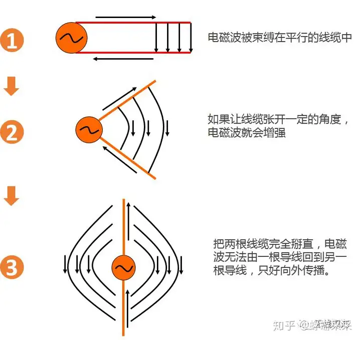
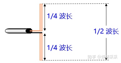
The above two wires that generate electromagnetic waves are called “oscillators”. In general, the size of the vibrator works best when it is half a wavelength, so it is often called a “half-wave vibrator”.
With the vibrator, electromagnetic waves can be emitted continuously. As shown below.
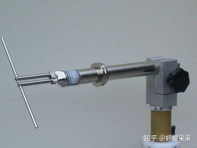
The real vibrator looks like the picture below.
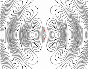
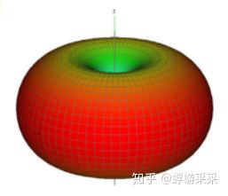
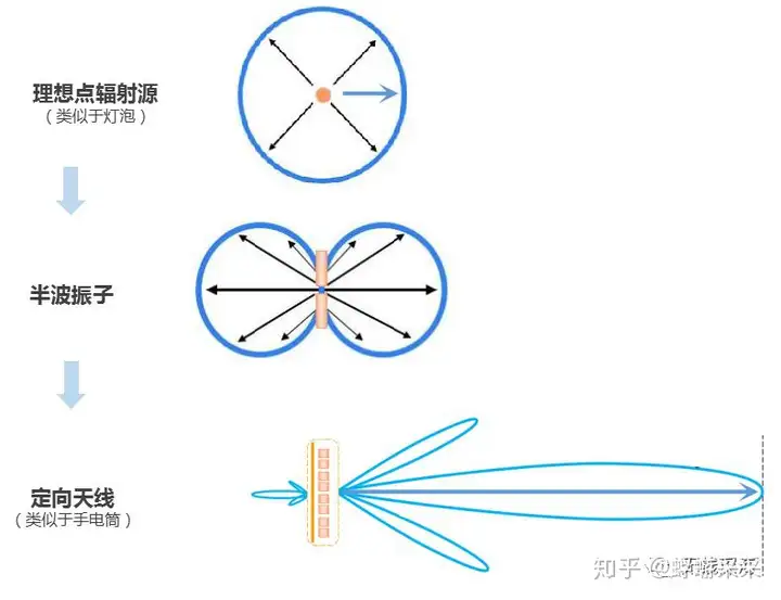
The half-wave vibrator continuously propagates electromagnetic waves into space, but the distribution of signal strength in space is not uniform, like a ring like a tire.
But in fact, the coverage of our base station needs to be farther in the horizontal direction. After all, people who need to make calls are on the ground; Coverage is another topic, I will talk about it next time), therefore, in the emission of electromagnetic wave energy, it is necessary to strengthen the horizontal direction and weaken the vertical direction.
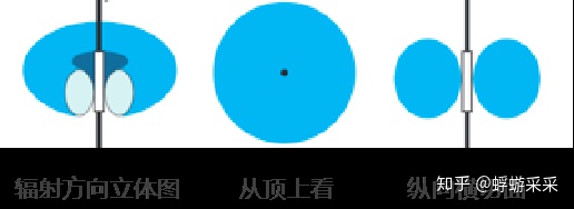
According to the principle of energy conservation, energy will neither increase nor decrease. If you want to increase the emission energy in the horizontal direction, you must weaken the energy in the vertical direction. Therefore, it is only necessary to flatten the energy radiation pattern of the standard half-wave array, as shown in the figure below.

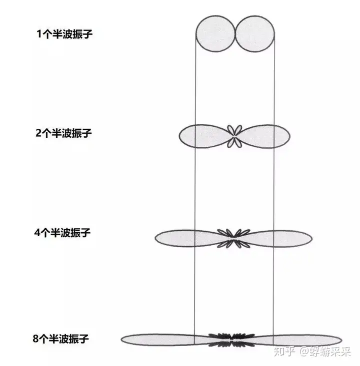
So how to flatten it? The answer is to increase the number of half-wave oscillators. The emission of multiple oscillators is gathered at the center, and the energy at the edge is weakened, so that the purpose of flattening the radiation direction and concentrating the energy in the horizontal direction is realized.
In general macro base station systems, the use of directional antennas is the most common. Generally, a base station is divided into 3 sectors and covered by 3 antennas, and each antenna covers a range of 120 degrees.
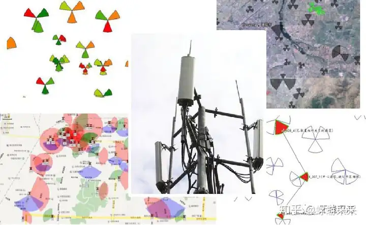
The above picture is a base station coverage planning map of an area. We can clearly see that each base station is composed of three sectors, and each sector is represented by a different color, which requires three directional antennas to realize.
So, how does the antenna realize the directional emission of electromagnetic waves?
This is certainly not a problem for smart designers. Wouldn’t it be enough to add a reflector to the vibrator to reflect the signal that should have been radiated to the other side?

In this way, the vibrator is added to make the electromagnetic wave spread farther in the horizontal direction, and the reflector is added to control the direction. After these two twists and turns, the prototype of the directional antenna is born, and the emission direction of the electromagnetic wave becomes as shown in the figure below.

The main lobe in the horizontal direction is far away from the emission ground, but the upper side lobe and the lower side lobe are produced in the vertical direction. At the same time, due to incomplete reflection, there is a tail behind it, called the back lobe.
At this point, the most important indicator of the antenna: the explanation of “gain” is a matter of course.
As the name implies, gain means that the antenna can enhance the signal. It stands to reason that the antenna does not need a power supply, but just emits the electromagnetic waves transmitted to it, so how can there be “gain”?
In fact, whether there is “gain” or not depends on who and how you compare with.
As shown in the figure below, compared with the ideal point radiation source and half-wave oscillator, the antenna can gather energy in the direction of the main lobe, and can send electromagnetic waves farther, which is equivalent to enhancing the direction of the main lobe. That is to say, the so-called gain is relative to a point radiation source or a half-wave oscillator in a certain direction.
So, how to measure the coverage and gain of the main lobe of the antenna? This requires the introduction of a “beam width” concept. We call the range where the electromagnetic wave intensity on both sides of the center line on the main lobe is attenuated to half as the beam width.
Because the intensity is attenuated by half, that is, 3dB, the beam width is also called “half power angle”, or “3dB power angle”.

Common antenna half-power angles are mostly 60°, and there are also narrower 33° antennas. The narrower the half power angle, the farther the signal propagates in the direction of the main lobe, and the higher the gain.
Next, we combine the horizontal pattern and the vertical pattern of the antenna to get the stereogram radiation pattern, which looks much more intuitive.
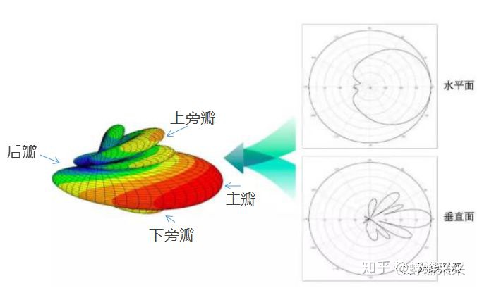
Obviously, the existence of the back lobe destroys the directivity of the directional antenna, which must be minimized as much as possible. The energy ratio between the front and back lobes is called the “front-to-back ratio”. The larger the value, the better, and it is an important indicator of the antenna.
The precious power of the upper side lobe is sent to the sky in vain, which is not a small waste, so when designing a directional antenna, try to suppress the upper side lobe to a minimum.
In addition, there are some holes between the main lobe and the lower side lobe, also known as the lower null, which leads to poor signal near the antenna. When designing the antenna, these holes should be minimized, which is called “zero filling”.
3. Be honest with the antenna
Let’s talk about another important concept of antennas: polarization.
As mentioned earlier, the propagation of electromagnetic waves is essentially the propagation of electromagnetic fields, and electric fields are directional.
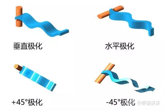
If the direction of the electric field is perpendicular to the ground, we call it a vertically polarized wave. Similarly, parallel to the ground is a horizontally polarized wave.
If the direction of the electric field forms an angle of 45° with the ground, we call it ±45° polarization.
Due to the characteristics of electromagnetic waves, it is determined that the horizontally polarized signal will generate a polarized current on the surface of the earth when it is close to the ground, so that the electric field signal is rapidly attenuated, while the vertically polarized mode is not easy to generate a polarized current, thereby avoiding energy loss. Significant attenuation ensures the effective transmission of signals.
As a compromise optimization solution, the current mainstream antennas are superimposed with two polarization modes of ±45°, and two oscillators form two orthogonal polarization waves in one unit, which is called dual polarization. While ensuring the performance, this implementation method also greatly improves the integration level of the antenna.
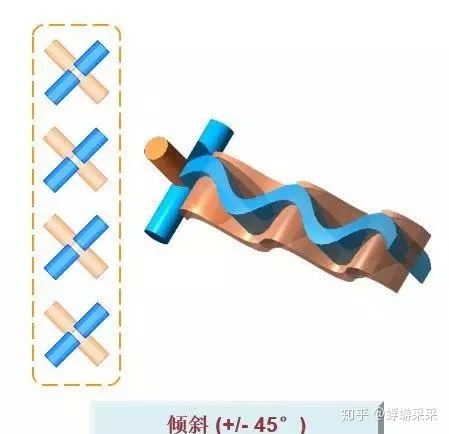
This is why I like to draw several crosses in the antenna schematic diagram. These crosses not only vividly represent the polarization direction, but also represent the number of oscillators.

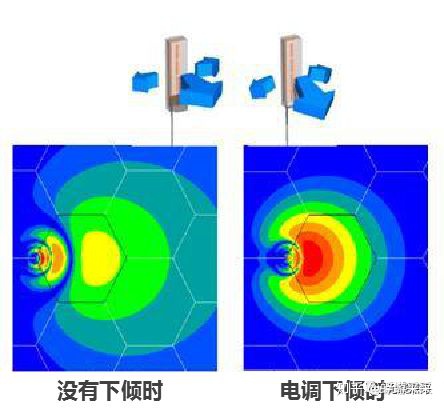
With a high-gain directional antenna, is it OK to hang it directly on the tower?
Obviously, if the ground is low, the building will block too much, so it won’t work; if the ground is high, there will be no one in the sky, which will waste the signal, and if the signal is transmitted too far, the base station can barely accept it, but the transmission power of the mobile phone is too small. I sent it to the base station and couldn’t receive it.
Therefore, this antenna has to transmit signals to the ground where there are people, and the coverage area must be controlled. This requires the antenna to be tilted down at an angle, like a street lamp, and each antenna is responsible for the coverage of its own area.
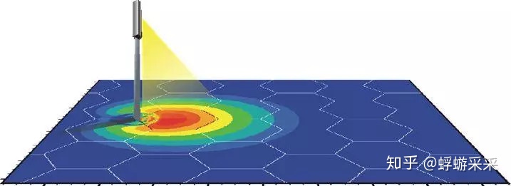
This introduces the concept of antenna downtilt.
All antennas have knobs with angle scales on their mounting brackets. By twisting the knobs to control the mechanical movement of the brackets, the downtilt angle can be adjusted. Therefore, adjusting the downtilt angle in this way is also called mechanical downtilt.
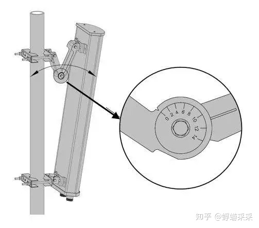
But this approach has two obvious drawbacks.
The first is trouble. In order to do network optimization and adjust an angle, engineers need to climb the tower on the station. It is hard to say how the actual effect will be, it is really inconvenient and costly.

The second is that the adjustment method of mechanical downtilt is too simple and rough, and the amplitude of the vertical component and horizontal component of the antenna remains unchanged, which will cause distortion of the coverage pattern.

After so much effort, the coverage before and after the adjustment completely changed, and it was difficult to achieve the expected effect, and the interference to other base stations also increased due to the upturning of the rear lobe, so the mechanical downtilt angle can only be adjusted slightly.
So, is there a better way?
There is really a way, that is, to use electronic downtilt. The principle of electronic downtilt is to change the phase of the collinear array antenna oscillator, change the amplitude of the vertical component and the horizontal component, and change the field strength of the composite component, so that the vertical pattern of the antenna is downtilted.
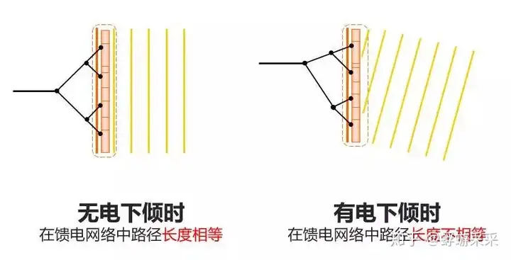
In other words, the electronic downtilt does not need to actually tilt the antenna, it only needs the engineer to click the mouse in front of the computer and adjust it with software. Moreover, electron downtilt does not cause distortion of the radiation pattern.
The simplicity and convenience of the electronic downtilt did not come out of thin air, but was realized through the joint efforts of the industry.
In 2001, several antenna manufacturers got together and established an organization called AISG (Antenna Interface Standards Group) to standardize the interface of electric adjustable antennas.

So far, there have been two versions of the agreement: AISG 1.0 and AISG 2.0.
With these two protocols, even if the antenna and the base station are produced by different manufacturers, as long as they comply with the same AISG protocol, they can transmit the control information of the antenna downtilt angle to each other to realize the remote adjustment of the downtilt angle.

With the backward evolution of the AISG protocol, not only the downtilt angle in the vertical direction can be adjusted remotely, but also the azimuth angle in the horizontal direction, as well as the width and gain of the main lobe can be adjusted remotely.
Moreover, due to the increasing number of wireless frequency bands of various operators, and the sharp increase in the number of antenna ports required by technologies such as 4G MIMO, antennas are gradually evolving from single-frequency dual-port to multi-frequency and multi-port.
The principle of the antenna seems simple, but the pursuit of performance excellence is endless. So far, this article has only qualitatively described the basic knowledge of base stations. As for the deeper mysteries inside, how to better support the evolution to 5G, waves of communication people are still searching up and down.
All that can be seen here is true love.
thank you all.

