Description: Analog signal, what does analog signal mean
What is an analog signal
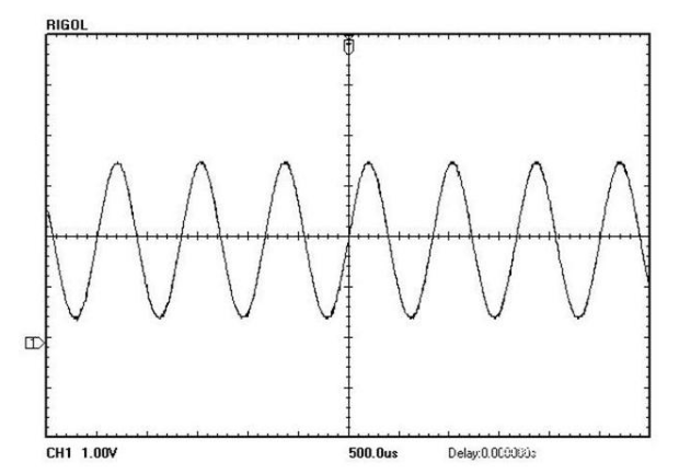
It is mainly a continuous signal as opposed to a discrete digital signal. Analog signals are distributed in every corner of nature, such as daily temperature changes, while digital signals are artificially abstracted signals that are discontinuous in time. Electrical analog signals mainly refer to electrical signals with continuous amplitude and phase. This signal can be subjected to various operations by analog circuits, such as amplification, addition, and multiplication.
Analog signals refer to information represented by continuously changing physical quantities, the amplitude, or frequency, or phase of the signal changes continuously over time, such as the current broadcast sound signal or image signal.
The difference between analog signal and digital signal
(1) Analog signal and digital signal
Different data must be converted into corresponding signals for transmission: analog data generally uses analog signals (Analog Signal), for example, a series of continuously changing electromagnetic waves (such as electromagnetic waves in radio and television broadcasting), or voltage signals (such as telephone transmission audio voltage signal) to represent; digital data is represented by a digital signal (Digital Signal), such as a series of intermittently changing voltage pulses (for example, we can use a constant positive voltage to represent binary number 1, and a constant negative voltage to represent binary Number 0), or light pulses to represent. When an analog signal is represented by a continuously changing electromagnetic wave, the electromagnetic wave itself is both a signal carrier and a transmission medium; and when an analog signal is represented by a continuously changing signal voltage, it is generally transmitted through a traditional analog signal transmission line (such as a telephone network). , cable television network) to transmit. When digital signals are represented by intermittently changing voltages or light pulses, it is generally necessary to use twisted-pair wires, cables, or optical fiber media to connect the communication parties to transmit signals from one node to another.
(2) Mutual conversion between analog signal and digital signal
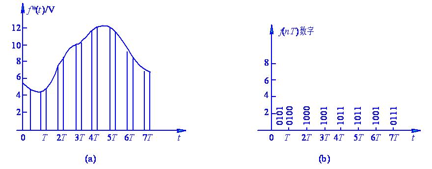
Analog signals and digital signals can be converted to each other: analog signals are generally quantized into digital signals by PCM pulse code modulation (Pulse Code Modulation) method, that is, different amplitudes of analog signals correspond to different binary values, for example, 8-bit encoding can The analog signal is quantized to 2^8=256 levels, and 24-bit or 30-bit encoding is often used in practice; digital signals are generally converted into analog signals by phase-shifting the carrier. Computers, computer local area networks, and metropolitan area networks all use binary digital signals. At present, what is actually transmitted in the computer wide area network is both binary digital signals and analog signals converted from digital signals. But what is more promising is the digital signal.
Digital Transmission of Analog Signals
The figure shows a schematic diagram of the simulation experiment of a simple delta modulation. The voice signal source in the figure is simulated by the output of a Gaussian noise source after passing through a 3KHz low-pass filter. Adjusting the gain of the icon 5 in the figure can change the magnitude of the difference Δ. At the receiving end, the demodulator does not use the same circuit as the local demodulator, but directly uses the integrator to demodulate the output. If you want the output waveform to be smooth, you can add a low-pass filter between the integrator and the output amplifier to filter out the high-frequency components in the signal. Shown is the input analog voice signal waveform. is the output waveform after delta modulation. is the output waveform after demodulation by the integrator. Observation allows comparison of distortion between input and output waveforms.
It can be seen from theoretical analysis that the quantized SNR of ΔM is in a cubic relationship with the sampling frequency, that is, the quantized SNR increases by 9dB every time the sampling frequency is doubled. Usually, the sampling frequency of ΔM is at least 16KHz to make the quantization signal-to-noise ratio more than 15dB. At 32KHz, the quantized signal-to-noise ratio is about 26dB, which can be used for general communication quality requirements. If the minimum signal-to-noise ratio available for the channel is 15dB, the dynamic range of the signal is only 11dB, which is far from meeting the 35-50dB dynamic range required by high-quality communication, unless the sampling frequency is increased to more than 100KHz for practical value. Readers can observe the conclusion of the above theoretical analysis by changing the signal sampling frequency of the simulation experiment. When the sampling frequency is lower than 16KHz, the signal distortion is very obvious, and when the sampling frequency is 128KHz, the distortion is relatively small.
There are many ways to improve the dynamic range of ΔM. The basic principle is to use an adaptive method to make the size of the magnitude Δ follow the change of the statistical characteristics of the input signal. If the magnitude scale can be companded instantaneously with the signal, it is called instantaneous companding ΔM, denoted as ADM. If the magnitude Δ changes with the average slope of the signal in the syllable time interval (5-20ms), it is called continuously variable slope incremental modulation, denoted as CVSD. Since the signal slope in this method is detected according to the number of consecutive “1”s or consecutive “0s” in the code stream, it is also called digital detection, adaptive incremental modulation of syllable companding, referred to as digital companding volume modulation. Figure 9.20 shows a block diagram of digitally-compressed amplitude modulation.
Compared with ordinary incremental modulation, the difference between digital companding incremental modulation lies in the addition of a “1” and “0” digital detection circuit and a syllable smoothing circuit. Since the adaptive information (that is, the control voltage) of CVSD is extracted from the output code stream, the receiving end does not need to transmit special adaptive information at the sending end to adapt to the original signal, and the circuit is relatively easy to implement. Readers who are interested in digital compression amplification modulation can add “1” to “0” digital detection circuit and syllable smoothing circuit on the basis of the above simulation experiment, re-simulate and observe the improvement.
