
This paper introduces and analyzes in detail the technical characteristics and trends of the development of digital TV transmitters in view of the upsurge of digital TV wireless transmission that has been set off around the world. Discusses the digital adaptive pre-correction technology, LDMOS technology, N+1 technology and transmitter cooling technology used in the digital TV transmitter and the advantages of using these new technologies.
Faced with the rapid development of GPS tracking, wireless Internet, mobile communication, PDP (plasma) display and TV studio technology, digital TV transmission technology seems to be slow. However, in recent years, driven by the digital TV market, the launch of digital TV services in countries such as the United Kingdom, the United States, Spain, and Canada, and the global upsurge of digital TV, TV transmission technology has also made great progress.
Early digital TV transmitters simply replaced the analog Vision/Sound exciter with an external COFDM or 8-VSB exciter, and replaced the RF output filter and Vision/Sound duplexer with an RF band filter. But recently, some large TV transmitter manufacturers have designed and produced a new generation of digital TV transmitters with new concepts and technologies. The main features are as follows:
Digital adaptive pre-correction technology (DAP or RTAC)
Digital adaptive pre-correction technology has been used in digital TV transmitters produced by manufacturers in the United States and Europe. THALES in Europe (formerly THOMCAST, a subsidiary of Thomson) calls it Digital Auto-Adaptive pre-correction (DAP for short); HARRIS in the United States calls it automatic digital correction—real-time Adaptive correction (Enter Automatic Digital Correction—Real Time Adaptive Correction, RTAC for short). Digital self-adaptive correction technology refers to adjusting the performance of the transmitter to the best state within a few minutes of just starting the transmitter without manual intervention. Moreover, this system can also monitor and automatically correct the data from the transmitter. The aging, temperature, and failure of the transmitter itself can be adjusted to ensure that the transmitted signal is always in a high-level state, making maintenance very simple.
High-power LDMOS transistors are widely used in power amplifiers
LDMOS (Lateral Diffused Metal Oxide Semiconductor) is: laterally diffused metal oxide semiconductor. At first, LDMOS technology was developed for 900MHz cellular phone technology. The continuous growth of the cellular communication market ensures the application of LDMOS transistors, and also makes LDMOS technology mature and cost continuously reduced. Therefore, it will replace bipolar transistors in most cases in the future. transistor technology.
Compared with bipolar transistors, the gain of LDMOS transistors is higher, and the gain of LDMOS transistors can reach more than 14dB, while the gain of bipolar transistors is 5~6dB, and the gain of PA modules using LDMOS transistors can reach about 60dB. This means that fewer components are required for the same output power, thereby increasing the reliability of the power amplifier. LDMOS can withstand a standing wave ratio 3 times higher than bipolar transistors, and can operate at higher reflected power without destroying LDMOS devices; it can withstand overdrive of input signals and is suitable for transmitting digital signals because it has Advanced instantaneous peak power. LDMOS gain curves are smoother and allow multi-carrier digital signal amplification with less distortion. LDMOS transistors have a low and unchanged intermodulation level to the saturation region, unlike bipolar transistors where the intermodulation level is high and varies with increasing power levels. This key characteristic allows LDMOS transistors to perform twice as much power as bipolar transistors with better linearity. LDMOS transistors have good temperature characteristics, and the temperature coefficient is negative, so it can prevent the influence of heat dissipation. This temperature stability allows amplitude variation of only 0.1dB, while in the case of the same input level, bipolar transistor amplitude variation from 0.5~0.6dB, and usually requires a temperature compensation circuit.
New LDMOS transistors with higher power. For transmitter engineers, more power per transistor means fewer transistors for a single power amplifier and lower device cost. The latest LDMOS FETs are capable of covering the entire UHF band. That is to say, a power amplifier module can operate at any frequency in the UHF band without adjustment, so that the TV station has fewer spare parts. It should be noted that not all so-called “broadband” power amplifiers work in the entire UHF band, and some require two or even three types of amplifiers to cover the entire band. The reason is to sacrifice gain to meet bandwidth. Higher gain means fewer transistors and lower cost, but at reduced bandwidth means two or three types of power amplifiers are needed to cover the entire TV band.
The use of these new transistors allows the manufacture of reliable and economical transmitters of higher power. Only a few years ago, in the UHF band more than 20KW (digital machine average power 5KW) vacuum tubes were almost dominant, followed by bipolar power amplifiers. Solid-state machines rarely use LDMOS, but with the continuous maturity of LDMOS technology and technology and the continuous decline in prices, as well as the incomparable advantages of bipolar transistors, there are good reasons to believe that high-power transmitters using LDMOS solid-state devices will become mainstream.
N+1 systems make stations with multiple transmitters more economical
N+1 means to use 1 transmitter to backup multiple (N units). Originally, solid-state transmitters are accumulated redundantly with relatively unstable equipment such as amplifiers and power supplies. Modular exciters generally adopt the form of automatic switching of double exciters, which significantly improves the reliability of equipment operation. Under normal circumstances, there is no need for backup like the electron tube and klystron transmitters. Because all solid-state digital TV transmitters use building block power amplifiers and power supplies running in parallel to implement N+1 systems, and most of them support hot swapping. In fact, the N+1 system has been used in FM broadcast transmitter systems for many years, and until now this technology has been used in TV transmitters, which can make stations with multiple transmitters more economical.
The cooling system adopts wind and liquid cooling options
In order to meet the needs of different customers for cooling systems, transmitter manufacturers have developed air-cooled and liquid-cooled systems. When customers purchase and place orders, users can choose the cooling method that suits them. Way. For example, the VHF OPTIMUM and UHF ULTIMATE series transmitters launched by THALES have already adopted this technology. From the author’s point of view, the liquid cooling method is more suitable for the national conditions because: a) The domestic air quality is poor, and dust is easy to deposit in the filter material, and the daily maintenance of the air cooling system is large. b) Reduced operating noise of the transmitter. c) Purified the environment of the transmitter room.
d) Reduced maintenance on the cooling system. The coolant circulates in a closed loop, requiring only regular cleaning of the filter in the system. e) High cooling efficiency. Whether the coolant is made of glycol (ethylene glycol) plus water or antifreeze, its heat conduction efficiency is much greater than that of wind, and the temperature of the inlet water of the cooling system is about a few degrees different from the temperature of the outlet water, so that the heat generated by the transmitter can be absorbed and released in time .
Wireless connection, GUI interface, fault self-diagnosis and remote control
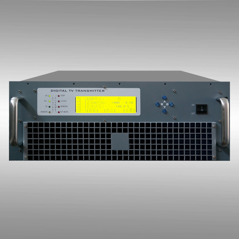
In the newly designed digital TV transmitter, the power amplifier, power supply and RF synthesizer save the cable and are directly connected together by plugging and unplugging. In this way, the structure of the whole machine is more compact and the maintenance is more convenient. The application of the microprocessor is able to monitor the status of the transmitter and provide useful information for each component. The LCD application provides an intuitive and friendly graphical user interface (GUI) to make user operations easier, and users can intuitively check the operating status of the device. The advanced fault self-diagnosis system and DAP technology make it easy for the user to find the fault location and speed up the maintenance and repair progress of the equipment. The remote control function enables users to monitor and control the equipment through the Internet.
Digital TV transmitters with the above-mentioned new technologies have been launched one after another. From the perspective of equipment management, this new equipment reduces capital and operating costs; from the perspective of TV engineers, this new equipment will save time and can be viewed from the web Transmitter running status, and transmitter settings. It can be predicted that in the next few years, in the process of gradually launching terrestrial digital TV and introducing digital TV transmitters in our country, the development trend mentioned above will become more obvious, and newer and more practical technologies will also appear.


