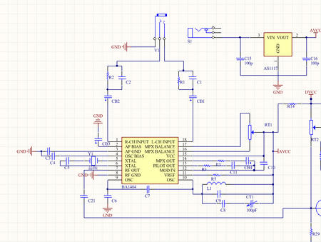
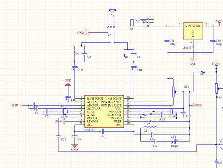
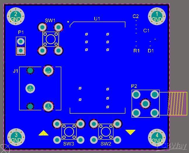
The circuit board diagram is as follows:
Description:
How to Build a Digital Coilless (100KHz Step Size) FM Transmitter
FM transmitters are one of the most popular devices among electronics hobbyists, professionals and even non-techies. In this article, we will learn how to build a simple, stable and digitally controllable FM transmitter.

For this design, I chose the VMR6512 module, it really is like a complete RF module on a chip! It eliminates all necessary circuitry of a basic FM transmitter, such as inductors and trimmers. According to the VMR6512 datasheet: “The VMR6512 is a highly integrated FM audio signal transmitting module. It integrates an advanced digital signal processor (DSP), frequency synthesizer, RF power amplifier and matching network. Therefore, no external components are required to Realize FM audio modulation. The VMR6512 can also achieve broadcast-quality sound quality through digital pre-emphasis, digital filtering, automatic gain control, and digital frequency control technology.”
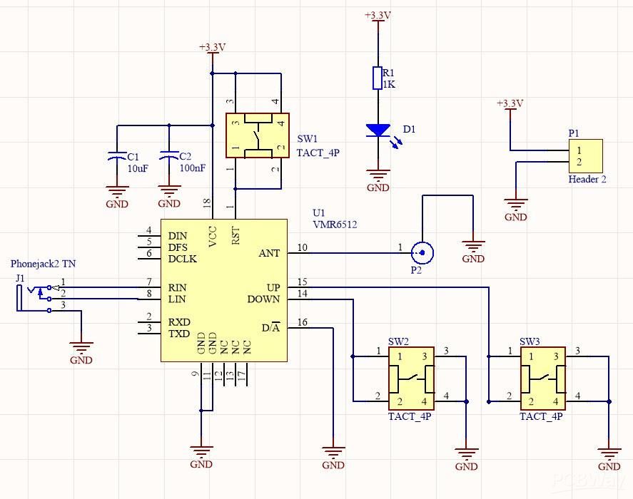
The operating frequency range is between 88.0MHz and 108.0MHz. Figure 1 shows a schematic diagram of the transmitter.
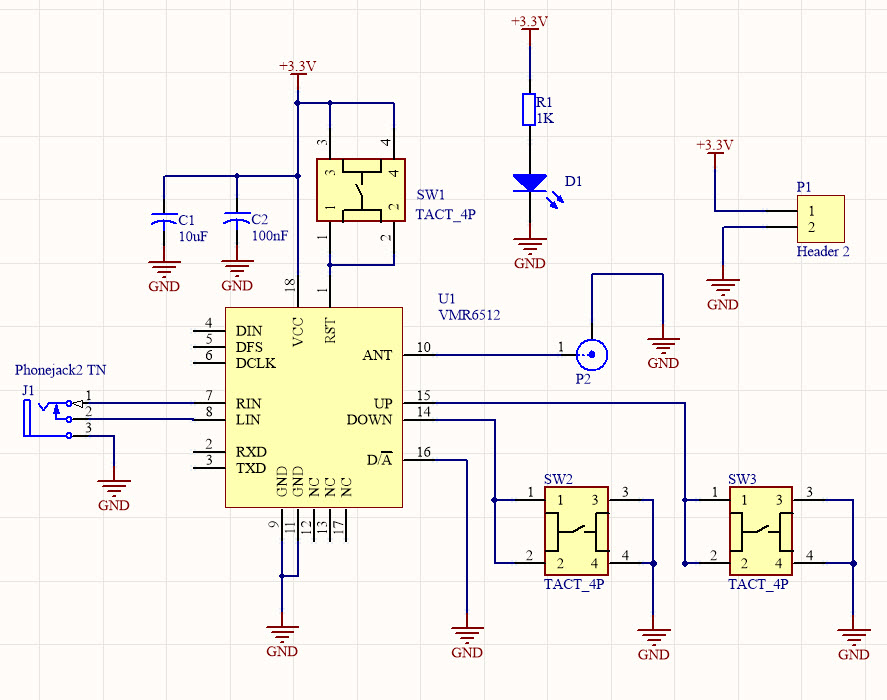
figure 1
FM Transmitter Schematic
