
The polarization of the antenna is an important theory of the antenna, which mainly refers to the direction of the electric field strength formed when the antenna radiates.
1,The concept of circular polarization of the antenna
The circular polarization of the antenna refers to: when the angle between the polarization plane of the radio wave and the normal plane of the earth changes periodically from 0 to 360 degrees, that is, the magnitude of the electric field remains constant and the direction changes with time, the trajectory of the end of the electric field vector When the projection on a plane perpendicular to the direction of propagation is a circle, it is called circular polarization. →
When the amplitude of the horizontal component and the vertical component of the electric field are equal, and the phase difference is 90 degrees or 270 degrees, circular polarization can be obtained. In circular polarization, if the polarization plane rotates with time and forms a right-hand spiral relationship with the electromagnetic wave propagation direction, it is called right-hand circular polarization; otherwise, if it forms a left-hand spiral relationship, it is called left-hand circular polarization. After understanding the concept of circular polarization, we go directly to the topic, how to circularly polarize the Yagi antenna.
2.Circular polarization of Yagi antenna
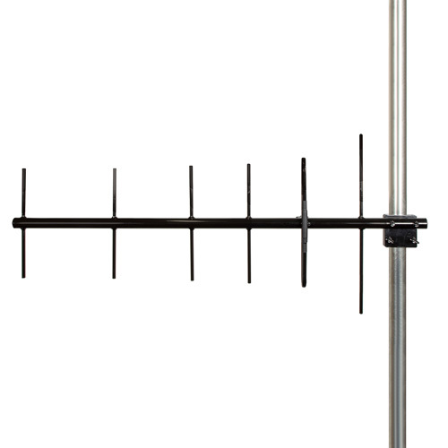
400MHz~470MHz 10dBi Yagi antenna, N-type female connector, adjustable polarization
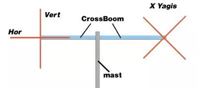
Among the various types of antennas, the helical antenna is very easy to achieve the required circular polarization due to its construction. Of course, in the field of Yagi antennas, this can also be achieved. The specific form is shown in the figure below:
This method of erection is called “Cross-Yagis” and refers to two identical Yagi antennas, the first in a vertical position and the second in a horizontal position. The angle between these two antennas must always be 90°, so it is also possible to place these antennas in an “X” position with the first at 45° and the second at 135°.
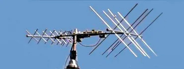
The figure below shows a typical arrangement with VHF and UHF “Cross-Yagis” antennas that can be used for LEO satellite communications.

If the beam is made of non-metallic material (such as wood, PVC, etc.), there will be no noticeable effect between the CrossBoom and Horizontal (horizontal) antennas, so in this case, the two antennas can be installed as a “+” type installation. If it is a metal beam, an “X” type installation is required.
The antennas of these two installation methods can use the switcher to switch the polarization. If necessary, one can be vertically polarized (for local communication), horizontally polarized (for long-distance communication) and circularly polarized (for If it is changed between satellite communication), then the “+” word installation has certain advantages. Only a minimum number of coaxial relays are required to enable the system to “switch” between vertical-horizontal-RHCP polarizations, whereas the “X” configuration requires more coaxial relays (and phase cables) to achieve.


