Antennas are an essential part of wireless transmission. Except that we use optical fibers, cables, network cables, etc. to transmit wired signals, as long as the signals are transmitted by electromagnetic waves in the air, various forms of antennas are required.
Basic Principles of Antennas
The basic principle of the antenna is that high-frequency currents generate changing electric and magnetic fields around it. According to Maxwell’s electromagnetic field theory, “changing electric fields generate magnetic fields, and changing magnetic fields generate electric fields.”
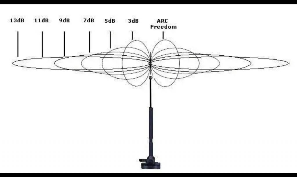
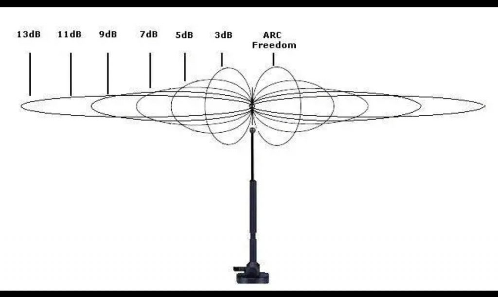
Gain factor
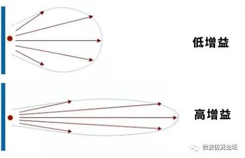
The ratio of the total input power of the antenna is called the maximum gain coefficient of the antenna. It is a more comprehensive reflection of the effective use of the total radio frequency power by the antenna than the antenna directivity coefficient. And expressed in decibels. It can be deduced mathematically that the maximum gain coefficient of the antenna is equal to the product of the antenna directivity coefficient and the antenna efficiency.
antenna efficiency
It refers to the ratio of the power radiated by the antenna (that is, the power that effectively converts the electromagnetic wave part) to the active power input to the antenna. is a value that is always less than 1.
antenna polarized wave
When electromagnetic waves propagate in space, if the direction of the electric field vector remains fixed or rotates according to a certain rule, this electromagnetic wave is called polarized wave, also known as antenna polarized wave, or polarized wave. Usually can be divided into plane polarization (including horizontal polarization and vertical polarization), circular polarization and elliptical polarization.
Polarization direction
The direction of the electric field of a polarized electromagnetic wave is called the direction of polarization.
polarized plane
The plane formed by the polarization direction and propagation direction of the polarized electromagnetic wave is called the polarization plane.
vertical polarization
The polarization of radio waves often takes the earth as the standard plane. Any polarized wave whose polarization plane is parallel to the earth normal plane (vertical plane) is called vertically polarized wave. The direction of its electric field is perpendicular to the earth.
horizontal polarization
Any polarized wave whose plane of polarization is perpendicular to the normal plane of the earth is called a horizontally polarized wave. The direction of its electric field is parallel to the earth. the
plane polarization
If the polarization direction of the electromagnetic wave is kept in a fixed direction, it is called planar polarization, also called linear polarization. In the component of the electric field parallel to the earth (horizontal component) and the component perpendicular to the earth’s surface, its spatial amplitude has any relative magnitude, and plane polarization can be obtained. Both vertical and horizontal polarization are special cases of planar polarization.
circular polarization
When the angle between the polarization plane of the radio wave and the normal plane of the earth changes from 0 to 360°, that is, the magnitude of the electric field is constant and the direction changes with time, the trajectory of the end of the electric field vector is on a plane perpendicular to the direction of propagation When the projection is a circle, it is called circular polarization. Circular polarization can be obtained when the horizontal and vertical components of the electric field have equal amplitudes and a phase difference of 90° or 270°. In circular polarization, if the polarization plane rotates with time and forms a right-hand spiral relationship with the electromagnetic wave propagation direction, it is called right-hand circular polarization; otherwise, if it forms a left-hand spiral relationship, it is called left-hand circular polarization.
elliptical polarization
If the angle between the radio wave polarization plane and the earth normal plane changes periodically from 0 to 2π, and the trajectory of the end of the electric field vector is projected as an ellipse on a plane perpendicular to the propagation direction, it is called elliptical polarization. Elliptic polarization can be obtained when the amplitude and phase of the vertical and horizontal components of the electric field have arbitrary values (except when the two components are equal).
Long wave antenna, medium wave antenna
It is a general term for transmitting antennas or receiving antennas working in the long wave and medium wave bands. Long and medium waves are propagated by ground waves and sky waves, while sky waves are continuously reflected between the ionosphere and the earth. According to this propagation characteristic, long and medium wave antennas should be able to generate vertically polarized radio waves. Among the long and medium wave antennas, vertical, inverted L, T, and umbrella vertical ground antennas are widely used. The long and medium wave antennas should have a good ground grid. Long and medium wave antennas have many technical problems, such as small effective height, small radiation resistance, low efficiency, narrow passband, and small directivity coefficient. In order to solve these problems, the antenna structure is often very complex and bulky.
short wave antenna
Transmitting or receiving antennas that work in the short-wave band are collectively referred to as short-wave antennas. Short waves are mainly propagated by means of sky waves reflected by the ionosphere, and are one of the important means of modern long-distance radio communication. There are many forms of short-wave antennas, among which the most widely used are symmetrical antennas, in-phase horizontal antennas, double-wave antennas, angular antennas, V-shaped antennas, rhombus antennas, and herringbone antennas. Compared with the long-wave antenna, the short-wave antenna has a large effective height, large radiation resistance, high efficiency, good directivity, high gain, and wide bandwidth.
ultrashort wave antenna
Transmitting and receiving antennas that work in the ultrashort wave band are called ultrashort wave antennas. Ultrashort waves mainly rely on space waves to propagate. There are many forms of this antenna, among which Yagi antenna, dish cone antenna, biconical antenna, “bat wing” TV transmitting antenna and so on are the most widely used.
microwave antenna
Transmitting or receiving antennas working in the meter wave, decimeter wave, centimeter wave, millimeter wave and other bands are collectively referred to as microwave antennas. Microwaves mainly rely on space waves to propagate. In order to increase the communication distance, the antennas are erected higher. Among microwave antennas, parabolic antennas, horn parabolic antennas, horn antennas, lens antennas, slotted antennas, dielectric antennas, and periscope antennas are widely used.
Directional antenna
A directional antenna refers to an antenna that transmits and receives electromagnetic waves particularly strongly in one or several specific directions, while transmitting and receiving electromagnetic waves in other directions is zero or extremely small. The purpose of using a directional transmitting antenna is to increase the effective utilization of radiation power and increase confidentiality; the main purpose of using a directional receiving antenna is to increase the anti-jamming capability.
non-directional antenna
Antennas that radiate or receive electromagnetic waves uniformly in all directions are called non-directional antennas, such as whip antennas for small communication machines.
broadband antenna
An antenna whose directivity, impedance, and polarization characteristics remain almost constant over a wide band is called a broadband antenna. Early broadband antennas include rhombic antennas, V-shaped antennas, double wave antennas, disc-conical antennas, etc., and new broadband antennas include logarithmic periodic antennas.
tune antenna
Antennas with predetermined directivity only in a narrow frequency band are called tuned antennas or tuned directional antennas. Typically, the directivity of a tuned antenna remains constant only in the 5% band around its tuning frequency, while at other frequencies the directivity changes so much that communications are disrupted. Tuned antennas are not suitable for short-wave communications with variable frequencies. In-phase horizontal antennas, folded antennas, meander antennas, etc. are all tuned antennas.
vertical antenna
A vertical antenna is one that is placed perpendicular to the ground. It has two forms, symmetrical and asymmetrical, and the latter is widely used. Symmetrical vertical antennas are often center-fed. The asymmetric vertical antenna is fed between the bottom of the antenna and the ground, and its maximum radiation direction is concentrated in the ground direction when the height is less than 1/2 wavelength, so it is suitable for broadcasting. Asymmetric vertical antennas are also called vertical ground antennas.
inverted L antenna
An antenna formed by connecting a vertical downconductor to one end of a single horizontal conductor. Because it looks like the English letter L upside down, it is called an inverted L-shaped antenna. The Γ character of the Russian alphabet is exactly the reverse writing of the English letter L. Therefore, it is more convenient to call the Γ-type antenna. It is a form of vertically grounded antenna. In order to improve the efficiency of the antenna, its horizontal part can be composed of several wires arranged on the same horizontal plane. The radiation generated by this part is negligible, and the vertical part generates radiation. Inverted L antennas are generally used for long-wave communications. Its advantages are simple structure and convenient erection; its disadvantages are large footprint and poor durability.
T-shaped antenna
In the center of the horizontal wire, a vertical down-lead wire is connected, which is shaped like the English letter T, so it is called a T-shaped antenna. It is the most common type of vertically grounded antenna. Its horizontal part radiates negligibly, and it is the vertical part that radiates. In order to improve efficiency, the horizontal part can also be composed of multiple wires. The characteristics of the T-shaped antenna are the same as those of the inverted L-shaped antenna. It is generally used for long-wave and medium-wave communications.
umbrella antenna
On the top of a single vertical wire, several inclined conductors are drawn down in all directions, and the antenna formed in this way is shaped like an open umbrella, so it is called an umbrella antenna. It is also a form of vertically grounded antenna. Its features and uses are the same as inverted L-shaped and T-shaped antennas.
whip antenna
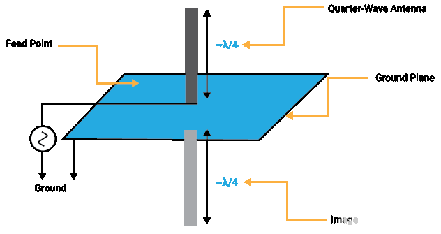
A whip antenna is a bendable vertical rod antenna that is typically 1/4 or 1/2 wavelength in length. Most whip antennas use a ground mesh instead of a ground wire. Small whip antennas often use the metal casing of a small radio as the ground grid. Sometimes in order to increase the effective height of the whip antenna, some small radial blades can be added to the top of the whip antenna or an inductor can be added to the middle end of the whip antenna. Whip antennas can be used in small communicators, walkie-talkies, car radios, etc.
symmetrical antenna
The two parts are equal in length and the center is disconnected and connected to the feed wire, which can be used as a transmitting and receiving antenna. The antenna formed in this way is called a symmetrical antenna. Because the antenna is sometimes called a vibrator, the symmetrical antenna is also called a symmetrical vibrator, or a dipole antenna. A symmetrical oscillator with a total length of half a wavelength is called a half-wave oscillator, also called a half-wave dipole antenna. It is the most basic unit antenna, and it is also the most widely used. Many complex antennas are composed of it. The structure of the half-wave vibrator is simple, the feeding is convenient, and it is widely used in short-distance communication.
cage antenna
It is a wide-band weak directional antenna. It is formed by replacing the single-wire radiator in the symmetrical antenna with a hollow cylinder surrounded by several wires. Because the radiator is cage-shaped, it is called a cage antenna. The cage antenna has a wide operating band and is easy to tune. It is suitable for short-distance trunk communication.
angle antenna
It belongs to the category of symmetrical antenna, but its two arms are not arranged in a straight line, but form an angle of 90° or 120°, so it is called angular antenna. This kind of antenna is generally installed horizontally, and its directivity is not obvious. In order to obtain wide-band characteristics, the arms of the angular antenna can also adopt a cage structure, which is called an angular cage antenna.
folding antenna
A symmetrical antenna that bends the vibrator to be parallel to each other is called a folded antenna. There are several forms of double-wire folded antenna, three-wire folded antenna and multi-line folded antenna. When bending, the currents at the corresponding points on each line should be in the same phase. From a distance, the entire antenna looks like a symmetrical antenna. However, compared with the symmetrical antenna, the folded antenna has enhanced radiation. The input impedance is increased to facilitate coupling with the feeder. A folded antenna is a tuned antenna with a narrow operating frequency. It is widely used in shortwave and ultrashortwave bands.
V-shaped antenna
It is composed of two wires at an angle to each other, and is shaped like an antenna of the English letter V. Its terminal can be open or connected with a resistor whose magnitude is equal to the characteristic impedance of the antenna. The V-shaped antenna is unidirectional, and the maximum emission direction is in the vertical plane in the direction of the subdivision line. Its disadvantages are low efficiency and large footprint.
Rhombus Antenna
It is a broadband antenna. It consists of a horizontal rhombus suspended on four pillars, one acute angle of the rhombus is connected to the feeder, and the other acute angle is connected to a terminal resistance equal to the characteristic impedance of the rhombus antenna. In the vertical plane pointing to the direction of the terminal resistance, it has unidirectionality.
The advantages of the rhombic antenna are high gain, strong directivity, wide band, and easy installation and maintenance; the disadvantage is that it occupies a large area. After the deformation of the rhombic antenna, there are three forms of double rhombic antenna, feedback rhombic antenna and folded rhombic antenna. Rhombus antennas are generally used for large and medium-sized shortwave receiving stations.
dish cone antenna
It is an ultrashort wave antenna. The top is a disc (that is, the radiator), which is fed by the core wire of the coaxial line, and the bottom is a cone, which is connected to the outer conductor of the coaxial line. The function of the cone is similar to the infinite ground. Changing the inclination angle of the cone can change the maximum radiation direction of the antenna. It has an extremely wide frequency band.
herringbone antenna
The fishbone antenna, also known as the side-fire antenna, is a special short-wave receiving antenna. It consists of connecting a symmetrical vibrator at a certain distance on two collective lines, and these symmetrical vibrators are all connected to the collective line through a small capacitor. At the end of the collective line, that is, one end facing the communication direction, a resistor equal to the characteristic impedance of the collective line is connected, and the other end is connected to the receiver through the feeder. Compared with the rhombus antenna, the advantage of the fishbone antenna is that the side lobe is small (that is, the receiving ability in the direction of the main lobe is strong, and the reception in other directions is weak), the mutual influence between the antennas is small, and the footprint is small; the disadvantage is the efficiency Low, complicated to install and use.
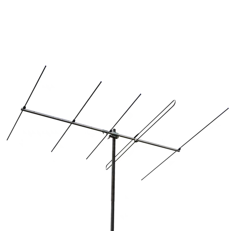
Yagi Antenna
Also called directed antenna. It consists of several metal rods, one of which is a radiator, the longer one behind the radiator is a reflector, and the shorter ones in front are directors. Radiators usually use folded half-wave oscillators. The maximum radiation direction of the antenna is the same as that of the director. The advantages of the Yagi antenna are simple structure, light and strong, and convenient feeding; the disadvantages are narrow frequency band and poor anti-interference. It is used in ultrashort wave communication and radar.
sector antenna
It has two forms of metal plate type and metal wire type. Among them, it is a fan-shaped metal plate type, and it is a fan-shaped metal wire type. This kind of antenna widens the frequency band of the antenna due to the enlarged cross-sectional area of the antenna. Wire sector antennas are available with three, four or five metal wires. Sector antennas are used for ultrashort wave reception.
biconical antenna
A biconical antenna consists of two cones with opposing apexes at which power is fed. The cone can be constructed of metal surfaces, wire or mesh. Just like the cage antenna, due to the increase in the cross-sectional area of the antenna, the frequency band of the antenna is also widened. Biconical antennas are mainly used for ultrashort wave reception.
parabolic antenna
The parabolic antenna is a directional microwave antenna, which consists of a parabolic reflector and a radiator. The radiator is installed on the focal point or focal axis of the parabolic reflector. The electromagnetic wave emitted by the radiator is reflected by the parabola to form a highly directional beam.
The parabolic reflector is made of metal with good conductivity. There are four main types: rotating paraboloid, cylindrical paraboloid, cut rotating paraboloid and elliptical edge paraboloid. The most commonly used are rotating paraboloid and cylindrical paraboloid. Radiators generally use half-wave oscillators, open waveguides, slotted waveguides, etc. the
The parabolic antenna has the advantages of simple structure, strong directivity, and wide operating frequency band. The disadvantages are: since the radiator is located in the electric field of the parabolic reflector, the reflector has a large reaction to the radiator, and it is difficult to get a good match between the antenna and the feeder; the back radiation is large; the protection degree is poor; the manufacturing precision is high. This antenna is widely used in microwave relay communication, troposcatter communication, radar and television.
horn parabolic antenna
The horn parabolic antenna consists of two parts: the horn and the parabola. The paraboloid covers the horn, and the apex of the horn lies at the focus of the paraboloid. The horn is a radiator, which radiates electromagnetic waves to the parabola, and the electromagnetic waves are reflected by the parabola, focused into a narrow beam and emitted. The advantages of the horn parabolic antenna are: the reflector has no reaction to the radiator, the radiator has no shielding effect on the reflected electric wave, the antenna and the feeding device are well matched; the back radiation is small; the protection degree is high; the working frequency band is very wide; the structure is simple. Horn parabolic antennas are widely used in trunk relay communications.
horn antenna
Also known as horn antenna. It is composed of a uniform waveguide and a horn-shaped waveguide whose section gradually increases. Horn antennas come in three forms: sectoral horn antennas, pyramidal horn antennas, and conical horn antennas. Horn antennas are one of the most commonly used microwave antennas and are generally used as radiators. Its advantage is the wide operating frequency; the disadvantage is that it is larger in size, and its directivity is not as sharp as that of the parabolic antenna for the same caliber.
horn lens antenna
It is composed of a horn and a lens mounted on the aperture of the horn, so it is called a horn lens antenna. For the principle of the lens, please refer to the lens antenna. This antenna has a fairly wide operating frequency band and has a higher degree of protection than the parabolic antenna. It is widely used in microwave trunk communications with a large number of channels.
lens antenna
In the centimeter band, many optical principles can be used for antennas. In optics, the use of a lens can make the spherical wave radiated by a point light source placed at the focal point of the lens become a plane wave after being refracted by the lens. Lens antennas are made using this principle. It consists of a lens and a radiator placed at the focal point of the lens. There are two kinds of lens antennas: dielectric deceleration lens antenna and metal deceleration lens antenna. The lens is made of low-loss high-frequency dielectric, thick in the middle and thin around. Spherical waves emitted from a radiation source are decelerated when passing through a dielectric lens. Therefore, the path of the deceleration of the spherical wave in the middle part of the lens is long, and the path of deceleration in the peripheral part is short. Therefore, the spherical wave becomes a plane wave after passing through the lens, that is, the radiation becomes directional. The lens is made of many metal plates of different lengths placed in parallel. The metal plates are perpendicular to the ground, and the metal plates closer to the middle are shorter. Electric waves in parallel metal plates
Accelerated during propagation. When the spherical wave emitted from the radiation source passes through the metal lens, the closer to the edge of the lens, the longer the accelerated path, and the shorter the accelerated path in the middle. Therefore, the spherical wave after passing through the metal lens becomes a plane wave. the
Lens antennas have the following advantages:
- The side lobe and back lobe are small, so the pattern is better;
- The precision of manufacturing the lens is not high, so the manufacturing is more convenient. Its disadvantages are low efficiency, complicated structure and high price. Lens antennas are used in microwave relay communications. slotted antenna One or several narrow slots are opened on a large metal plate and fed with a coaxial line or a waveguide. The antenna formed in this way is called a slot antenna, also known as a slot antenna. In order to obtain unidirectional radiation, the back of the metal plate is made into a cavity, and the slot is directly fed by the waveguide. The slotted antenna has a simple structure and no protruding parts, so it is especially suitable for use on high-speed aircraft. Its disadvantage is that it is difficult to tune. dielectric antenna The dielectric antenna is a round rod made of low-loss high-frequency dielectric material (generally polystyrene), and one end of it is fed with a coaxial line or a waveguide. 2 is the extension of the inner conductor of the coaxial line, forming a vibrator to excite electromagnetic waves; 3 is the coaxial line; 4 is the metal sleeve. The function of the sleeve is not only to clamp the dielectric rod, but also to reflect the electromagnetic wave, so as to ensure that the electromagnetic wave is excited by the inner conductor of the coaxial line and propagates to the free end of the dielectric rod. The advantage of the dielectric antenna is small size and sharp directivity; the disadvantage is that the medium has loss, so the efficiency is not high. periscope antenna In microwave relay communication, the antenna is often placed on a very high support, so a very long feeder must be used to feed the antenna. Too long feeder will cause many difficulties, such as complex structure, large energy loss, distortion caused by energy reflection at the feeder joint, etc. In order to overcome these difficulties, a periscope antenna can be used, which consists of a lower-mirror radiator placed on the ground and an upper-mirror reflector mounted on a bracket. The radiator of the lower mirror is generally a parabolic antenna, and the reflector of the upper mirror is a metal plate. The lower mirror radiator emits electromagnetic waves upwards, which are reflected by the metal plate. The advantages of periscope antennas are small energy loss, low distortion, and high efficiency. It is mainly used in microwave relay communication with small capacity. helical antenna is an antenna with a helical shape. It consists of a metal helix with good electrical conductivity, and is usually fed by a coaxial line. The core wire of the coaxial line is connected to one end of the helical line, and the outer conductor of the coaxial line is connected to the grounded metal mesh (or plate). connect. The radiation direction of the helical antenna is related to the circumference of the helix. When the circumference of the helix is much smaller than one wavelength, the direction of the strongest radiation is perpendicular to the helix axis; when the circumference of the helix is on the order of one wavelength, the strongest radiation appears in the direction of the helix axis. antenna tuner An impedance matching network connecting the transmitter and the antenna is called an antenna tuner. The input impedance of the antenna changes greatly with the frequency, while the output impedance of the transmitter is constant. If the transmitter is directly connected to the antenna, when the frequency of the transmitter changes, the impedance mismatch between the transmitter and the antenna will reduce the radiation. power. Using an antenna tuner, the impedance between the transmitter and the antenna can be matched so that the antenna has the maximum radiated power at any frequency. Antenna tuners are widely used in ground, vehicle, ship and aviation short-wave radio stations. log periodic antenna It is a broadband antenna, or a frequency-independent antenna. Among them, is a simple log-periodic antenna, and its dipole length and spacing conform to the following relationship: τ dipoles are fed by a uniform two-wire transmission line, and the transmission line needs to exchange positions between adjacent dipoles . This antenna has a characteristic: any characteristic at frequency f will be repeated at all frequencies given by τⁿf, where n is an integer. These frequencies are all equally spaced on a logarithmic scale, and the period is equal to the logarithm of τ. This is where the name of the logarithmic periodic antenna comes from. A log-periodic antenna simply repeats the radiation pattern and impedance characteristics periodically. But the antenna with such a structure, if τ is not much smaller than 1, the change of its characteristics in a cycle is very small, so it is basically independent of frequency. There are many types of log-periodic antennas, including log-periodic dipole antennas and monopole antennas, log-periodic resonant V-shaped antennas, and log-period helical antennas. The most common one is the log-period dipole antenna. These antennas are widely used in shortwave and above shortwave bands.
