
The mixer is a frequently used device in the audio and video industry. Today, I will show you the relevant knowledge of the mixer. The time is limited. This article mainly introduces the analog mixer.
In an audio sound reinforcement system, it is usually composed of three parts: audio source, peripheral processing equipment, and external amplifier.
Common audio sources: microphone, computer, DVD, etc.;
Processing equipment: mixer, media matrix, effects, feedback suppressor, etc.;
External equipment: power amplifier, speakers
Then we can see that the mixer is a processing device in the entire audio system.
What is a mixer.
The mixer has multiple input channels, the input channels have a microphone input port with low input impedance and low input level and a line input port with high input impedance and high input level; the signal of each input channel is subjected to voltage amplification and sound quality A device that processes, and can mix, process, distribute, and produce one or more outputs. *
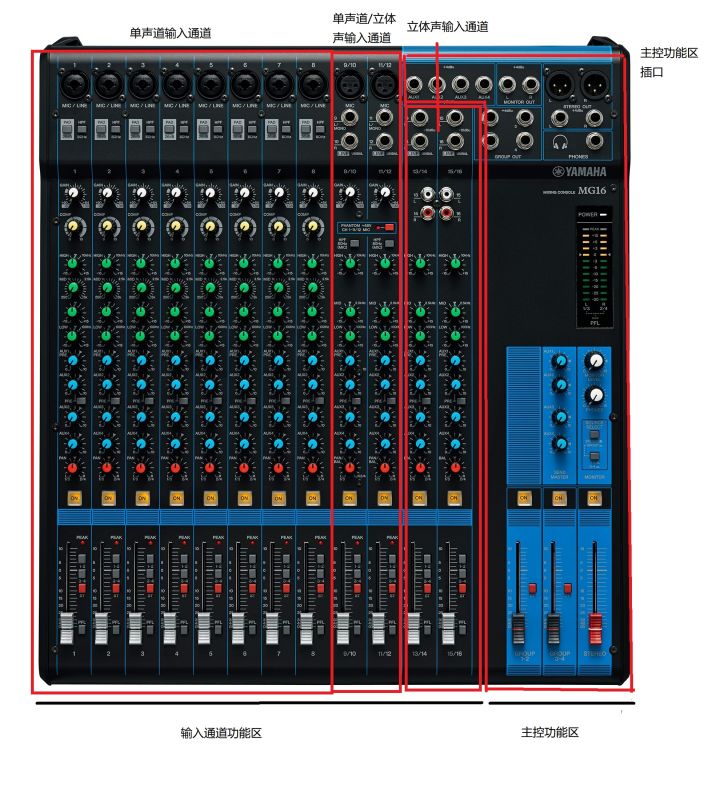
Mixer diagram (take Yamaha MG16 as an example)
We divide the mixer into master input channels, and these two parts have corresponding functional areas.
Input Channel Ribbon
①Mono input jacks: Channels 1-8 are all mono input jacks. The interfaces are MIC and LINE. The MIC port can be connected to an XLR (XLR) plug, and the LINE port can be connected to a phone-type (large pole) plug. Connect the microphone and/or instrument you want to use.

Mono input jack
Remarks: For XLR (XLR) plugs and phone-type (large pole) plugs, see the picture below
The MIC interface is to receive some lower level signals, such as: microphone, DI box.
The LINE interface is to receive some “line standard” signals, such as: CD players, musical instruments.

XLR female plug and XLR right plug
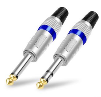
Phone type plug
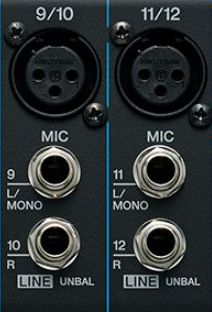
②Mono/stereo input jacks: 9/10, 11/12 are all, the MIC port can be connected to XLR (XLR) plugs, and the LINE (L/MONO, R) ports can be connected to phone-type plugs.
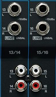
③Stereo input jacks: LINE (L, R) can be connected to phone-type plugs, and the white and red ones below can be connected to RCA (lotus) plugs.
④[PAD] switch

When this switch is turned on, the input signal of the [MIC/LINE] jack of the mono input channel will be attenuated by 26dB (this value varies, not necessarily 26dB). This switch should be turned off if a microphone or other low input level device is connected to the corresponding channel.
⑤ [HPF] (High Pass Filter) switch

When this switch is on, a high-pass filter is applied, attenuating frequencies below 80 Hz with a slope of 12 dB/octave.
Note: A high-pass filter is a system that makes high frequencies easier to pass and blocks low frequencies from passing. It removes unnecessary low-frequency components or low-frequency interference from the signal. Similarly, there are low-pass filters, and there will be high and low-pass filters in the media matrix at the same time.
⑥ [GAIN] knob

Used to adjust the gain of the input signal.
Remarks: What is gain? Explain the process of the mixer to pressurize the passing electrical signal. This process will be accompanied by the increase of the volume. Because it is pressurization, when the gain is adjusted too large, current may appear. ; And because the mixer is connected to different devices, the level of each device is inconsistent, and adjusting the gain can also ensure the same level of the connected devices.
⑦ [COMP] knob
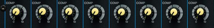
Adjusts the amount of compression applied to the channel.
Remarks: The main purpose is to reduce the dynamic range of the sound. Simply put, turn up the low volume and turn down the high volume, so that the loudness of the entire audio will not differ too much.
⑧ [PHANTOM +48V] switch and indicator

Use this switch to turn phantom power on or off, which when on applies DC+48 V power to the XLR input jacks. When the switch is on, the indicator lights up.
Remarks: Sometimes people ask me why the microphone does not need power supply. In fact, the microphone needs to be powered. If the external power supply is more troublesome, you can directly supply power to the microphone through the mixer with phantom power supply.
⑨Equalizer ([HIGH]/[MID]/[LOW])

The equalizer can adjust the channel’s high, mid and low frequency bands.
Remarks: Equalizer is an electronic device that can separately adjust the amount of electrical signal amplification of various frequency components. It can compensate for the defects of speakers and sound field by adjusting the electrical signals of various frequencies, compensate and modify various sound sources and other Special function, the equalizer on the general mixer can only adjust the electric signals of high frequency, intermediate frequency and low frequency respectively. A professional graphic equalizer divides the 20Hz~20kHz signal into 10, 15, 27, and 31 sections for adjustment.
⑩[AUX1-4] knob [PRE] switch
The signal level sent from each channel to the AUX 1 – 4 buses can be adjusted individually.

Sends the pre-fader (the signal before the fader adjustment) to the AUX bus when the [PRE] switch is on.
Remarks: Aux, the abbreviation of Auxiliary. Used to specify additional lines, usually used to send signals to effects, headphones, speakers and other equipment, for example, when Polan sings, input his voice from the mic into the mixer and connect an external The effect is processed by the effect, and then input to the mixer, we can hear the sound of the sound of the day.
①①[PAN] knob [PAN/BAL] knob [BAL] knob

PAN: Sets the position of the pan in the stereo sound field. This knob adjusts the volume balance of each channel sent to the STEREO L/R bus.
BAL: Sets the volume balance of the signal sent from each stereo input channel (L/R) to the STEREO L/R bus or GROUP bus.
PAN/BAL: This knob can provide both [PAN] and [BAL] functions. When sound is input to the [LINE] (L/MONO) jack, you can use it as a [PAN] controller, and when sound is input to both [LINE] (L) and [LINE] (R), it can be used as a [PAN] controller [BAL] Controller used.
Remarks: When two or more speakers are used for stereo playback, the listener’s impression of the sound position is sometimes called a phantom. The spatial distribution of the sound image is determined by the human binaural effect. .
①② [ON] switch

When the secondary switch is on, the corresponding channel’s signal can be sent to the bus output. Simply put, it can be understood as a mute button.
Note: To minimize noise, turn off the [ON] switch of any unused channel.
①③[PEAK] indicator

The peak level of the post-EQ signal is detected, and the PEAK indicator lights red when the level reaches 3dB below clipping.
Note: the sound will be distorted if the level is too high
①④Bus distribution switch
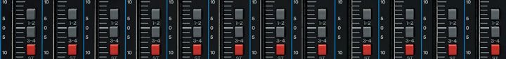
These switches determine the destination bus to which each channel’s signal will be sent.
[1-2] switch: Assign the channel’s signal to the GROUP 1-2 bus.
[3-4] switch: Assign the channel’s signal to the GROUP 3-4 bus.
[ST] switch: Assigns the channel’s signal to the STEREO L/R bus.
①⑤[PFL] (pre-fader monitor) switch

When the [PFL] switch is on, the channel’s pre-fader signal is output to the [MONITOR OUT] and [PHONES] jacks for monitoring.
①⑥Channel fader
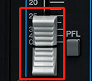
Used to adjust the level of the channel signal. Use these controls to adjust the balance between multiple channels.
Note: To minimize noise, turn the faders of unused channels to their lowest level.
main control area
[SEND] (send) jack
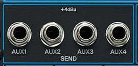
These jacks can be connected to monitoring systems such as external effects equipment or stage/studio. These are impedance balanced *phone type output jacks
Note: You can output the sound of the local conference site to the video conference terminal, recording host, etc.
②[GROUP OUT] jack
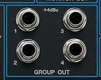
These impedance-balanced TRS phone jacks can output signals. Use these jacks to connect the inputs of a multitrack recorder, external mixer, or other such device.
③[MONITOR OUT] jack

Connect these impedance-balanced TRS phone jacks to your monitoring system.
④[STEREO OUT] jack
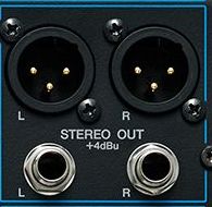
These are XLR-type and TRS phone-type balanced output jacks that can output mixed stereo signals. The signal level can be adjusted via the [STEREO] master fader before being output. For example, these jacks can be used to connect the power amplifiers driving the main speakers.
⑤[PHONES] jack

Needless to say, the headphones are on.
⑥[MONITOR] section
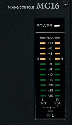

[POWER] indicator, needless to say, it will light up when power on;
Level meter:
The level meter LEDs show the signal level of the STEREO L/R, GROUP bus, or the signal level selected via the [PFL] switch. The “0” (<) segment corresponds to the nominal output level. The [PEAK] indicator lights up when the output signal reaches the clipping level.
[MONITOR LEVEL] knob
For adjusting the signal level output to the [MONITOR OUT] jack.
[PHONES] knob
For adjusting the signal level output to the [PHONES] jack.
[SOURCE]/[SOURCE SELECT] (Monitor signal selection switch)
Sets the signal sent to the [MONITOR OUT] jack, [PHONES] jack, and level meters. You can use this switch to select a signal from the STEREO L/R bus, GROUP 1-2 bus, or GROUP 3-4 bus.
⑦ [SEND MASTER] section
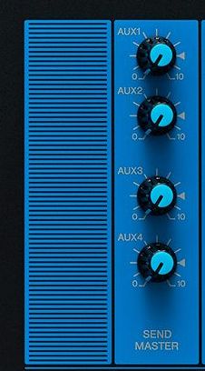
For adjusting the signal level output to the [SEND] jacks and [AUX1-4].
⑧[GROUP] section
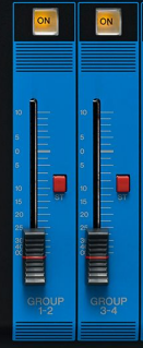
[ON] switch When this switch is on, the [GROUP] fader is enabled. The switch will illuminate when turned on.
[GROUP 1-4] faders
For adjusting the signal level output to the [GROUP OUT 1-4] jacks.
[ST] switch
If this switch is on, the signal will be sent to the STEREO L/R bus via the [GROUP 1-2, 3-4] faders. The GROUP1, 3 signals go to the Stereo L bus, and the GROUP 2, 4 signals go to the STEREOR bus.
⑨ [STEREO] section
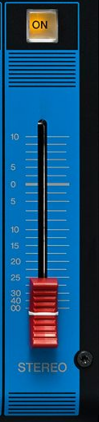
[ON] switch
When this switch is on, the [STEREO] master fader is enabled, and the switch lights when on.
[STEREO] Master fader
For adjusting the signal level output to the [STEREO OUT] jack.
Choice of mixer
For conference-based venues, it is not necessary to monitor the sound in real time. It is recommended not to use a mixer, but to use a media matrix. The media matrix can be connected to the central control or its own volume control panel. Users only need to adjust the volume of the sound. , which also avoids system problems due to misoperation.
In performance-based occasions, and there are specialized operators, it is necessary to configure the mixer.


