Click Here For: The Charm of FM Radio Broadcasting (Part 1)
7. The IF amplifier is the source of distortion
The intermediate amplifier is the core of the FM receiver. The indicators such as sensitivity, signal-to-noise ratio, capture ratio, distortion and selectivity are directly related to the performance of the intermediate amplifier. The FM intermediate amplifier is the place where new devices and technologies are most concentrated. The technologies that have been used on the device are as follows:
1) Ultra-linear solid-state filter: LC mid-cycle, quartz crystal, multi-mode ceramic and surface acoustic wave filters have been used in intermediate amplifiers. The LC mid-week is the oldest and classic device, and the combination of 4 to 6 loops can design the amplitude-frequency characteristic into a Butterworth or Gaussian type. In the early years, in order to improve the selectivity, the Butterworth type was used. Due to the poor group delay characteristics, the Gaussian type with good group delay characteristics became popular in machines that value sound quality. Crystal filters have the best squareness coefficients, but poor group delay characteristics. Ceramic filters are small in size and low in price. The early products have poor delay characteristics. Later products have been greatly improved, and they have become the mainstream of intermediate frequency filters. The disadvantage is that the center frequency varies greatly, and you need to choose a pairing. The amplitude-frequency characteristics and phase-frequency characteristics of the surface acoustic wave filter can be designed separately, and the group delay characteristics can be done well, but there are corresponding side lobes. In order to take into account the selectivity and distortion, a combination of various filters is generally used in the tuner. For example, the narrowband state uses crystal and ceramic filters to give priority to selectivity, the ordinary state uses ceramic filters and surface acoustic wave filters to take into account both sound quality and selectivity, and the broadband state uses LC filters to ensure sound quality and capture ratio.
▲ONKYO T727 radio tuner
2) Frequency Negative Feedback and Variable Parameter Middle Placement: The idea of frequency negative feedback is to reduce the frequency offset to narrow the distribution width of the sideband of the FM wave. When the frequency band is narrow, the group delay characteristic at the center frequency of the ceramic filter can be used as the flattest. A straight section of the curve to minimize distortion. And it can make 100% of the sideband pass through the filter to achieve full spectrum transmission. After the frequency offset is reduced, the high-frequency signal-to-noise ratio will decrease, so the frequency positive feedback is used after the filter to restore the frequency offset to 75KHz. This technology first appeared on Onkyo’s T-727 tuner, which uses only 6 decibels of frequency negative feedback and has a distortion degree of 0.1%. After that, Kenwood invented the spectrum-free technology on this basis, compressing the frequency offset to almost zero. This technology was applied to the famous L-02T tuner in history, and the distortion of the machine was reduced to 0.003%. Frequency negative feedback is to improve the linearity by changing the frequency offset parameter, and can also improve the signal-to-noise ratio by changing the frequency offset. Because the signal-to-noise ratio of the FM wave is proportional to the frequency offset, the frequency offset can be doubled with a simple frequency multiplier. For every doubling of the frequency offset, the signal-to-noise ratio increases by 6 dB. If the frequency multiplier is used, the frequency offset can be increased to 375 KHz, and the signal-to-noise ratio can be increased by 30 dB. The signal-to-noise ratio at 75KHz frequency offset is 65 decibels, and it is 95 decibels after 5 times of frequency, which is the same as the index of CD. After the frequency offset increases, the requirements on the linear range of the frequency discriminator also increase, so the frequency multiplier should not exceed 5 times. Another parameter that can be changed is the relative frequency offset, which can be changed to improve the frequency discrimination sensitivity. It is realized by the secondary frequency conversion, and the relative frequency deviation of the intermediate frequency frequency is increased. Wide linear discriminators tend to be less sensitive, and in this way the output amplitude of the discriminator can be increased.
3) Signal transformation: After changing the frequency offset, the FM intermediate frequency becomes a sparse and unequal pulse after frequency reduction and amplitude limiting. It can be transformed into a pulse width modulation (PWM) signal with a simple digital circuit, which is similar to CD and PWM. The one-bit quantized signal in a digital power amplifier is the same, but the modulation signal is not audio, but an MPX signal. If a digital discriminator is used, the IF signal will undergo this transformation. In software radio, the IF of 10.7MHz is directly sampled by ADC and processed by DSP. In the past, new technologies in mid-amplification, frequency discrimination and decoding can be implemented by software algorithms.
8. the key to the frequency discriminator is linearity and bandwidth
The frequency discriminator is the second largest source of distortion in the FM receiver. It can be seen from Table 2 that the frequency discriminator has a higher impact on the sound quality than the tuner and the decoder. In a tuner, the amplifier and the discriminator jointly determine its performance, so it is paid special attention by the manufacturer. In order to compete in the market, 11 kinds of frequency discriminators have been used in history, they are proportional frequency discriminator, phase frequency discriminator, phase-shift product frequency discriminator, PLL frequency discriminator, phase tracking frequency discriminator, Pulse Count Discriminator, Delay Line Discriminator, Differential Discriminator, PWM Discriminator, Digital Parametric Discriminator and DSP Discriminator. Manufacturers and designers exaggerate the advantages of their own frequency discriminators, and some circuits are touted. In order to evaluate the performance of these frequency discriminators, NHK used 12KHz audio frequency with a frequency offset of 5 to 10Hz, and scanned the passband of the frequency discriminators to check their linearity. Better, because no matter what the form of the frequency discriminator is, as long as the linearity and bandwidth meet the requirements, and the differential gain is a horizontal line, good sound quality can be obtained.
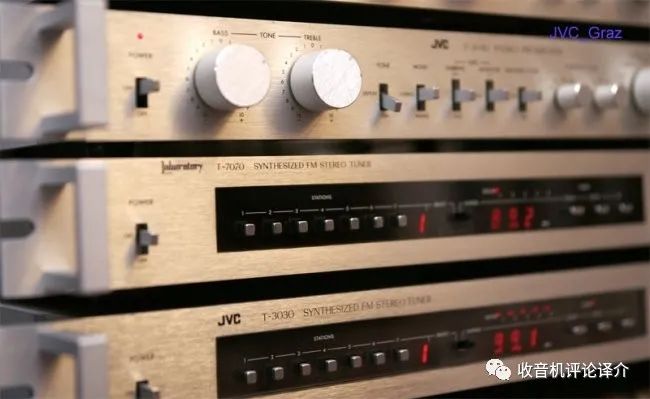
▲JVD T7070 broadcast tuner
How wide the frequency band and how good the linearity can meet the requirements of high-fidelity? In order to prevent IF detuning caused by temperature and offset errors, the linear bandwidth of the discriminator should be 100KHz higher than the IF bandwidth in ordinary radios, and should be higher than 200KHz in tuners. If there is a bandwidth option in the tuner, the broadband is generally 400KHz, and the narrowband is generally 200KHz, so the linear bandwidth of the frequency discriminator needs to reach 600KHz. In an analog circuit discriminator with a center frequency of 10.7MHz, the ratio and phase discriminators must use double-tuned loops to meet the requirements. It is also useful to use tracking technology to generate linear bandwidth. For example, the phase tracking frequency discriminator converts the FM wave into a phase-modulated wave, demodulates the MPX signal in the phase detector, and the reference signal of the phase detector is regenerated by a phase-locked loop. Due to the complexity of the circuit, Hitachi made it into the integrated circuit HA11211. JVC company favors this kind of circuit, and it is often seen on their mid-to-high-end tuners, such as T7070, JT-V77 and so on.
The situation is more complicated in the variable-parameter amplifier circuit, and it is necessary to treat the changed parameters specifically. When the frequency offset is changed, the bandwidth of the frequency discriminator will change accordingly. If the frequency offset changes to 150KHz, 225KHz, 300KHz, 375KHz, according to the calculation method of the Japanese Soujima, the corresponding linear bandwidth is 800KHz, 1.2MHz , 1.6MHz, 2MHz. It is difficult for the analog discriminator circuit to achieve a linear bandwidth above 600KHz, so it is implemented in a digital way. The simplest digital method is to convert the sine wave FM signal into a width modulated pulse, and use a low-pass filter to restore the MPX signal, such as a pulse count discriminator and a PWM frequency discriminator. This discriminator appeared on the AJ510 tuner of Heathkit Company in the United States in the early 1970s. After Trio learned it in 1976, it was used on all its high-end tuners. Another digital processing method is to down-convert the frequency-modulated intermediate frequency into a pulse below 2MHz, and demodulate the MPX signal with an XOR gate device through two CMOS gates with different delay times. The realization of digital frequency discrimination algorithm in DSP is very simple, it can be completed by quadrature signal multiplier, and there is no linearity and bandwidth problems. On DAB/FM tuners now, frequency discrimination and decoding are implemented in DSP with software algorithms.
Intermediate amplifiers and discriminators used to be a DIY paradise for radio enthusiasts. There are many classic circuits with clever ideas and excellent performance, which are still talked about by many enthusiasts today.
9. the most assured is the stereo decoder
▲The one sitting in the center is Mr. Wang Xincheng
Today, whether it is a factory-made FM radio or a DIY FM radio, the most reliable part of the stereo decoder. Even with a two-battery-powered laptop, a TA7343 decoder can easily get 40dB of stereo separation. In the past, this was almost unthinkable.
Historically, it took twenty years to improve the stereo separation of receivers. In the pilot frequency system, the amplitude difference and phase difference between the sum signal and the difference signal; the phase difference between the regenerated subcarrier and the transmitter subcarrier will affect the separation degree. If the sum-difference signal has an amplitude difference of 3 decibels or a phase difference of 20 degrees, the regenerated sub-carrier phase and the original sub-carrier have a phase difference of 20 degrees, and the stereo effect will disappear without a trace. In the decoder, phase difference and amplitude difference exist at the same time, and these parameters also change with temperature and time. Stereo decoders are available in two forms: matrix type and switch type. The matrix type is simple in principle and easy to implement, but has strict requirements on circuits and devices, which is destined to be a matrix decoder designed with electronic tubes or transistors in the early years. degree of separation. I have tested the high-priced high-end stereo radios in history, and the separation is generally around 12 decibels, which is far less than the hand-held radios sold on the stalls today. In principle, the switching decoder can obtain a higher degree of separation, but requires regenerating a switching signal that has no phase difference with the subcarrier at the transmitting end. The switching signal without phase-locked loop regeneration can not meet the phase requirements, so the switching decoder can not get a high degree of separation, the highest is about 20 decibels. Therefore, in the more than 20 years after the FM stereo was broadcast, the degree of separation has always been the weakness of the FM receiver.
In the early years, when Europeans and Japanese were having headaches for stereo separation, in 1972, Motorola of the United States developed the world’s first integrated phase-locked loop stereo decoder MC1310, and the stereo separation jumped from ten decibels to 40 decibels. , the distortion is reduced from 1% to 0.3%. after. Various Japanese manufacturers have learned to imitate and produced a variety of decoders with better performance. For example, the TA7343 commonly used in cheap machines has a separation of 45 decibels, a distortion of 0.08%, and a signal-to-noise ratio of 74 decibels. The stereo decoder specially used in the tuner has achieved 65dB separation, 0.006% harmonic distortion, and 89dB signal-to-noise ratio. Stereo in FM radios has only lived up to its name since the advent of this device. And breaking the boundaries of advanced and popular, people have to sigh the progress of technology and the changes of the times.
10. can not ignore the low frequency preamplifier
▲Mr. Wang Xincheng and Shanghai radio enthusiasts
Although the low frequency preamplifier is in an inconspicuous position in the tuner, its role cannot be ignored as part of the receiver. In an excellent tuner, it should have the following functions:
1) De-emphasis circuit: In the mono receiver, the 50-microsecond de-emphasis circuit is connected after the frequency discriminator. In the stereo receiver, in order to ensure that the pilot and difference signals are not attenuated, the de-emphasis circuit is connected to the stereo. after the decoder.
2) Pilot and sub-carrier frequency filters: The main purpose is to remove the residual pilot and sub-carrier frequency components in the audio and prevent intermodulation distortion in the low-frequency amplifier. They also produce bird calls when recording and AD-converting and beating the bias and sampling frequencies.
3) Noise suppression circuit: The gain of the FM receiver is very high, and there will be a lot of noise when there is no signal input. In the past, the squelch was mainly set to avoid noise when tuning, and locations without stations were still quiet. There is no tuning noise in digital memory tuning. Since many receivers retain the manual tuning of the flywheel, the squelch circuit is still necessary.
4) Equal loudness control: Compensate for the defect of narrowing of the auditory frequency response at low volume according to the human ear’s hearing equal loudness curve. This function can obtain rich high and low bass effects when used as home background music at low volume.
5) Tone Control: To be used to compensate for the imperfections of the speakers and the listening environment
6) Passband control: Listening to FM broadcasts in the edge areas where the signal is weak, setting the bandwidth of the low-frequency circuit at 150-8000Hz can significantly reduce high-frequency noise.
7) Intimacy control: Properly increasing the amplitude in the range of 2000-3000Hz can make the human voice feel intimacy, and appropriately limiting the rate of the low-frequency amplifier can weaken the articulation and enhance the softness of the sound.
11. FM radio is not suitable for listening with Hi-Fi headphones
When listening to FM radio with Hi-Fi headphones, the sound is always a bit rough, with hissing noise and crackling discharge at program intervals and at low levels, which is the inherent noise floor of FM radio. 99.9% of the interference from outside sky power, industrial and household appliances can be suppressed by the limiter of the mid-amp and the frequency discriminator, and the rest of the parasitic FM, thermal noise of the transistor and flicker noise limiter Nothing can be done, they will add to the audio signal and become the noise floor.
So why can’t I hear the noise floor with the speakers? There are two reasons for this. One is that the weight of the headphone voice coil and diaphragm is very light. If a pair of headphones and a speaker are also marked with a sensitivity of 90 decibels, the headphones are driven by 1 milliwatt of electrical power to obtain a sound pressure of 90 decibels at a centimeter; the speaker is driven by 1 watt of electrical power at a distance of 1 from the speaker. The same sound pressure can be obtained at meters, and obviously the sensitivity of headphones is thousands of times higher than that of speakers. Another reason is that in the direction of sound transmission, the sound energy passing through a unit area is inversely proportional to the square of the distance, and the sound frequency increases from 1KHz to 10KHz, the frequency increases 10 times, but the absorption loss of air increases 100 times. The energy of low-level interference and noise is distributed in the middle and high frequency bands of the audio frequency, and attenuates very quickly in the air, almost attenuating to zero at a distance of one meter. Distance and air act as filters, making background interference and noise completely invisible to the human ear. Listening with headphones is completely different. The distance between the eardrum and the headphones is very close, which is equivalent to bypassing the noise floor filter. In addition, the sensitivity of the headphones is very high, so that the music and noise can be absorbed in our ears, making us feel the sound. rough.
In addition, the adaptability of speakers and earphones to music and the psychological feeling of listening are also different. Speakers are suitable for appreciating the spirit, such as symphony, concerts and operas. In the show, the soul-shaking Beth, the soft and sweet midrange, and the gorgeous and bright treble will induce the listener to feel the overall outline of the music, and have no time to take care of the details. Headphones are suitable for appreciating details, such as the sobbing violin and erhu, the invisible triangle and so on. Sweet vocals and nuanced highs induce the listener to feel the melody and technique of the music, capturing rich layers and subtler differences. Therefore, the old experience is to listen to CDs with headphones and listen to the radio with speakers.
12. Embracing the digital tomorrow
FM radio has been carrying music and happiness for 66 years. In the last century, radio enthusiasts in our country were not lucky to enjoy music FM. After the reform and opening up, FM radio stations have sprung up everywhere. However, two regrets have plagued the majority of fans: one is that the broadcast content is mixed, the local and county-level FM stations are not only poor in equipment, but also can’t compliment the program content. Another pity is that there is no good receiver to enjoy the broadcast. Since the Central People’s Broadcasting Station put forward the reform slogan “frequency specialization, management frequency” in 2002, the Voice of China, the Voice of the Economy, and the Voice of Music have successively launched, and local radio stations have also followed up and reformed their broadcast programs. After carefully comparing the FM radio stations in Shanghai, the sound quality of the 107.7MHz Sound of Music is the best; the content of the 94.7MHz classic music is the best, but unfortunately the transmission power is the smallest. Qiujiang Road Electronic Market and Xiangyang Road Modern Electronic Mall can find cheap and good used tuners.
Although FM broadcasting is facing the end of being replaced by digital broadcasting, the quality of broadcasting has reached its peak now, and both DAB and IBOC will be bit rate compressed in the future replacement system. Theoretically speaking, what compresses is redundant signals, but listening evaluation is a complicated matter, and the conclusions drawn in theory and laboratory cannot cover the individual psychological and physiological differences of each person. DAB broadcasting in the UK has become very popular, and European enthusiasts have carefully compared the sound quality of DAB and FM, and questioned the propaganda of DAB’s crystal-like sound. No matter what kind of digital broadcasting our country adopts in the future, the inherent nostalgia of human beings will surely make many people miss the FM broadcasting that brought us endless joy. A pastor in the Gospel Church once taught me: “To cherish today, only today is the most beautiful”.
